En-19
7.6.2 Procedures to enable automatic address setting on indoor
units
Check that the rotary switch IU AD on the indoor unit PC board is set to “00”.If it is not set
to “00”, it means the address of that device is not set. (Factory default is “00”).
Turn on the power of the indoor and outdoor units.
• When the system is normal, nothing will be displayed on the 7-segment display.
• When ERROR is displayed, inspect the units.
Use the “MODE/EXIT”, “SELECT”, and “ENTER” buttons on the outdoor unit PC board to
configure settings according to the procedures below.
1: Function setting
(The display when the main power is turned on)
Set to Function mode [F3].
(When [F4] to [F9] are displayed, continue to press
the “SELECT” button until [F3] is displayed.)
Press the “SELECT” button until “11” is displayed.
Press the “ENTER” button for more than 3 seconds.
End
The number of indoor units with normal settings will be
displayed at the first 2 digits of the 7-segment LED display.
The number of indoor units with error will be displayed at
the last 2 digits.
NOTE:
After the “ENTER” button is pressed, the end processing
will occur for about 30 seconds. During this period, the
7-segment will blink.
Automatic address setting for
indoor units
First 2 digits Last 2 digits
7.7. Resistance measurement of transmission cable
(Measure with breaker OFF)
CAUTION
Do not turn on the power if the resistance
between the terminals of the transmission
cable is abnormal. Otherwise, the PC
board may be damaged.
Measure the resistance between 2 termi-
nals of a transmission cable.
(1) Transmission cable connecting
indoor units, outdoor units, and
signal amplifiers
Measure the resistance of the signal
amplifier terminal and the terminal of
the indoor and outdoor units con-
nected farthest away from the device
where terminal resistor is measured.
A value from the table is displayed,
depending on the distance from the
signal amplifier and the device where
the terminal resistor is set.
This value is an estimate.
(2) Transmission cable connecting out-
door units in a refrigerant system
The resistance between the terminals
of the transmission cable is 45-60 Ω.
This value is an estimate.
Distance from termination resistor
(m)
0~100 ~200 ~300 ~400 ~500
Approximate resistance (Ω)
0 ~
50
A short circuit somewhere or 2
or more termination resistors are
connected
50
60
70
80
90
100
110
120
130
140
150
160
170
180
190
~
Faulty contact or wiring length over
500 m
1K
~∞
Faulty contact, open circuit, or no
termination resistor
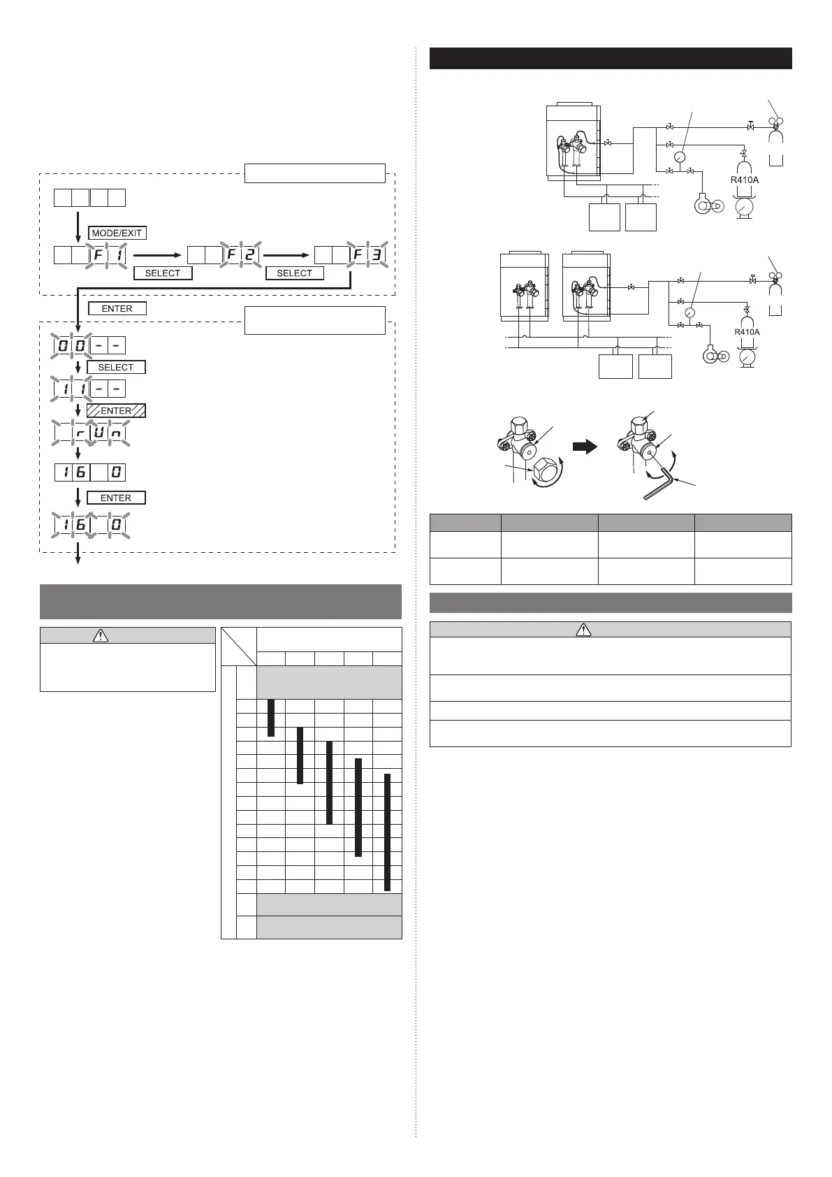
8. PIPE INSTALLATION II
Fig. A Connection system
In case of connected 1
outdoor unit
Outdoor unit
Pressure gauge
Vacuum
pump
Scale
Pressure regulating valve
Nitrogen
Indoor
unit
Indoor
unit
In case of con-
nected many
outdoor units
Pressure regulating valve
Pressure gauge
Outdoor unit Outdoor unit
Nitrogen
Scale
Vacuum
pump
Indoor
unit
Indoor
unit
Fig. B
Charging cap
Valve
Cap
Close
Hexagon
wrench
Close
Open
Open
Spindle
Table. A
Valve type Spindle Cap Charging cap
Liquid
9.0 to 12.0 N·m
(90 to 120 kgf·cm)
20.0 to 24.0 N·m
(200 to 240 kgf·cm)
12.5 to 16.0 N·m
(125 to 160 kgf·cm)
Suction gas
Discharge gas
27.0 to 33.0 N·m
(270 to 330 kgf·cm)
25.0 to 30.0 N·m
(250 to 300 kgf·cm)
12.5 to 16.0 N·m
(125 to 160 kgf·cm)
8.1. Sealing test
CAUTION
Use only nitrogen gas.
Never use refrigerant gas, oxygen, in flammable gas or poisonous gas to pressurize the
system. (If oxygen is used, there is the danger of an explosion.)
Do not apply shock during sealing test.
It can rupture the pipes and cause serious injury.
Do not turn on the power unless all operations are complete.
Do not block the walls and the ceiling until the sealing test and the charging of the
refrigerant gas have been completed.
After connecting the pipes, perform a sealing test.
Recheck that the 3-way valve are closed before performing a sealing test. (Fig. B)
Pour nitrogen gas through both the liquid pipe and the gas pipe.
Pressurize nitrogen gas to 4.2 MPa to perform the sealing test.
Check all flare connection areas and brazed areas.
Then, check that the pressure has not decreased.
Compare the pressures after pressurizing and letting it stand for 24 hours, and check that
the pressure has not decreased.
* When the outdoor temperature changes 5 °C, the test pressure changes 0.05 MPa.
If the pressure has dropped, the pipe joints may be leaking.
If a leakage is found, immediately repair it and perform a sealing test again.
* Decrease the pressure of nitrogen gas before blazing
After completing the sealing test, release the nitrogen gas from both valves.
Release the nitrogen gas slowly.
9378945708-02_IM_L9.indb 199378945708-02_IM_L9.indb 19 2022/1/20 15:34:392022/1/20 15:34:39

 Loading...


