En-7
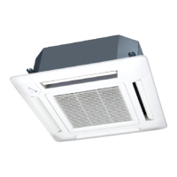
6.3.2. Transmission and Remote controller cable
Transmission cable Remote controller cable
Shield
cable
(no film)
30 mm
40 mm
30 mm
• Connect remote controller and transmission cables as shown in the figure below.
GOOD
Different diameter
Connect to 1 side
PROHIBITED
WARNING
Tighten the terminal screws to the specified torques, otherwise, abnormal overheating
may be produced and possibly cause heavy damage inside the unit.
Tightening torque
M3 screw (Transmission /X1, X2)
(Remote controller /Y1, Y2)
0.5 to 0.6 N•m (5 to 6 kgf•cm)
CAUTION
To peel the film from the lead cable, use a dedicated tool that will not damage the
conductor cable.
When installing a screw on the terminal block, do not cut the wire by overtightening the
screw. On the other hand, an undertightened screw can cause faulty contact, which will
lead to a communication failure.
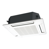
6.4. Connection of wiring
(1) Remove the control box cover and install each connection cable.
Screw
Control box cover
(2) Connect the connection cable, with the cable tie.
Cable clamp
L, N:
Power supply cable
Y1,Y2: Remote
controller cable
Cable tie (Medium)
(Accessories)
X1, X2:
Transmission cable
(3) Install control box cover.
CAUTION
Do not bundle the remote controller cable, or wire the remote controller cable in parallel,
with the indoor unit connection cable (to the outdoor unit) and the power supply cable. It
may cause erroneous operation.
6.5. Optional parts wiring
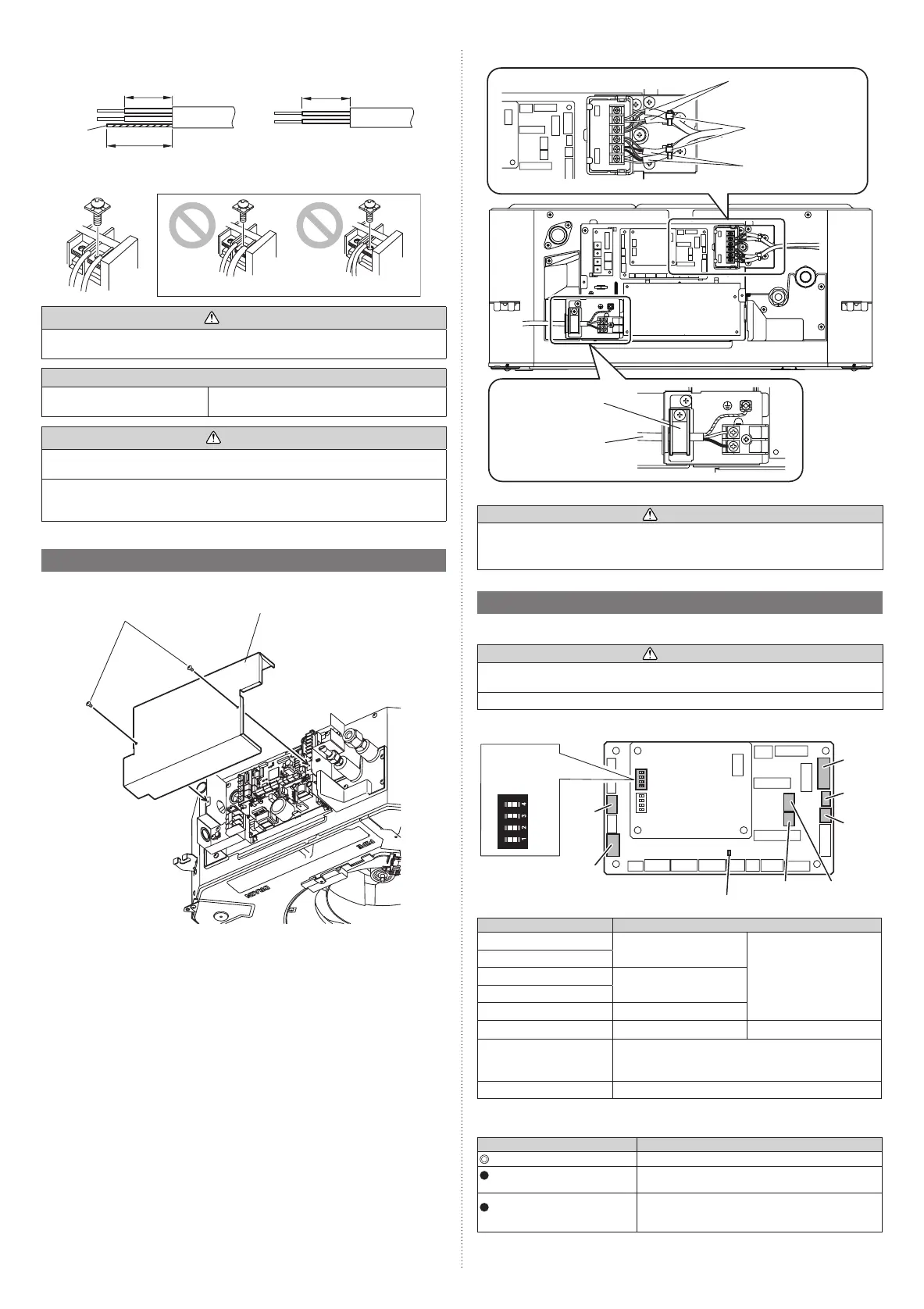
6.5.1. Layout of the indoor unit PCB
CAUTION
Do not operate any switches other than prescribed, as it can cause the unit to operate
improperly or malfunction.
Use an insulated screwdriver to set the DIP switches.
CN820
CN65
SW1
SW2
SW3
SW4
CNB01
CNA01
CNA03
CNA02CNA04
Controller PCB
DIP switch
(SET 2)
ON OFF
Power indicator lamp (green)
Name Application
CNA01
Apply voltage terminal For external input
CNA03
CNA02 Dry contact terminal
CNA04
DIP switch SET 2 (SW2) Input signal type switching
CNB01 Output terminal For external output
CN65 For one of the following.
• MODBUS® convertor (*1)
• Wireless LAN adapter (*1)
CN820 For External power supply unit (*1)
*1: For details, refer to each installation manual.
6.5.2. Power indicator lamp status
Power indicator lamp (Green) Status contents
Lit Lit when the power is turned on.
Fast flashing (every 0.1 sec-
ond)
There is a fault with the communication board or the
main board.
Blinking (repeat 3 seconds ON
and 1 second OFF)
The indoor unit is turned off and power is supplied
from the External power supply unit (optional) to the
indoor unit PCB.
9371022635-01_IM.indb 7 08/02/2019 17:03:23

 Loading...