Do not remove refrigerant, even if the additional amount calculated is negative.
sd
Indoor unit
(24,000 Btu)
Outdoor unit
(54,000 Btu)
Indoor unit
(24,000 Btu)
Liquid pipe [mm] 9.52
Gas pipe [mm] 15.88
Liquid pipe [mm] 9.52
Gas pipe [mm] 15.88
Liquid pipe [mm] 9.52
Gas pipe [mm] 15.88
(Example 1)
L2 : 10 m
L1 : 20 m
L3 : 7 m
Liquid pipe diameter
[mm]
Piping length
[m]
Coefcient
12.70 0 A = 0
9.52 37 B = 37
6.35 0 C = 0
Additional charging amount
Applying the formula,
(0 x 100) + (37 x 50) + (0 x 30) - 1500 = 350
The additional charging amount is 350 g.
Liquid pipe diameter
[mm]
Piping length
[m]
Coefcient
12.70 10 A = 10
9.52 0 B = 0
6.35 15 C = 15
Additional charging amount
Applying to the formula,
(10 x 100) + (0 x 50) + (15 x 30) - 1500 = –50
The calculated value is negative. Do not add or remove any refrigerant.
(Example 2)
Indoor unit
(18,000 Btu)
Indoor unit
(18,000 Btu)
Outdoor unit
(54,000 Btu)
Indoor unit
(18,000 Btu)
Liquid pipe [mm] 6.35
Gas pipe [mm] 12.70
Liquid pipe [mm] 6.35
Gas pipe [mm] 12.70
Liquid pipe [mm] 6.35
Gas pipe [mm] 12.70
Liquid pipe [mm] 12.70
Gas pipe [mm] 15.88
L3 : 5 m
L1 : 10 m
L4 : 5 m
L2 : 5 m
sd
6. ELECTRICAL WIRING
6.1. Notes for electrical wiring
WARNING
Wiring connections must be performed by a qualied person in accordance with
the specications. The voltage rating for this product is 400 V at 50 Hz. It should be
operated within the range of 342 to 456 V.
Before connecting the wires, make sure the power supply is OFF.
Use a dedicated power supply circuit. Insufcient power capacity in the electrical circuit
or improper wiring may cause electric shock or re.
Install a breaker at the power supply for each outdoor unit. Improper breaker selection
can cause electric shock or re.
Install a leakage circuit breaker in accordance with the related laws and regulations. An
improperly installed electrical box cover can cause serious accidents such as electric
shock or re through exposure to dust or water.
A circuit breaker is installed in the permanent wiring. Always use a circuit that can trip
all the poles of the wiring and has an isolation distance of at least 3 mm between the
contacts of each pole.
Use designated cables and power cables. Improper use may cause electric shock or re
by poor connection, insufcient insulation, or over current.
Do not modify power cable, use extension cable or branch wiring. Improper use may
cause electric shock or re by poor connection, insufcient insulation or over current.
Connect the connector cable securely to the terminal. Check no mechanical force bears
on the cables connected to the terminals. Faulty installation can cause a re.
Use crimp-type terminals and tighten the terminal screws to the specied torques,
otherwise, abnormal overheating may be produced and possibly cause serious damage
inside the unit.
WARNING
Make sure to secure the insulation portion of the connector cable with the cable clamp.
Damaged insulation can cause a short circuit.
Fix cables so that cables do not make contact with the pipes (especially on high
pressure side). Do not make power supply cable and transmission cable come in
contact with valves (Gas).
Never install a power factor improvement condenser. Instead of improving the power
factor, the condenser may overheat.
Be sure to perform the earthing (grounding) work.
Do not connect earthing (grounding) wires to a gas pipe, water pipe, lightning rod or
earthing (grounding) wire for a telephone.
Connection to a gas pipe may cause a re or explosion if gas leaks.•
Connection to a water pipe is not an effective earthing (grounding) method if PVC •
pipe is used.
Connection to the earthing (grounding) wire of a telephone or to a lightning rod may •
cause a dangerously abnormal rise in the electrical potential if lightning strikes.
Improper earthing (grounding) work can cause electric shocks.
Securely install the electrical box cover on the unit. An improperly installed service panel
can cause serious accidents such as electric shock or re through exposure to dust or
water.
CAUTION
The primary power supply capacity is for the air conditioner itself, and does not include
the concurrent use of other devices.
Do not start operation until the refrigerant is charged completely. The compressor will
fail if it is operated before the refrigerant piping charging is complete.
Transmission cable between indoor unit and outdoor unit is 230 V.
Be sure not to remove thermistor sensor etc. from power wiring and connection wiring.
Compressor may fail if operated while removed.
Start wiring work after closing branch switch and over current breaker.
Use an earth leakage breaker that is capable of handling high frequencies. Because the
outdoor unit is inverter controlled, a high-frequency earth leakage breaker is necessary
to prevent a malfunction of the breaker itself.
When using an earth leakage breaker that has been designed solely for earth (ground)
fault protection, be sure to install a fuse-equipped switch or circuit breaker.
Do not connect the AC power supply to the transmission line terminal board. Improper
wiring can damage the entire system.
Do not use crossover power supply wiring for the outdoor unit.
If the temperature surrounding the breaker is too high, the amperage at which the
breaker cuts out may decrease.
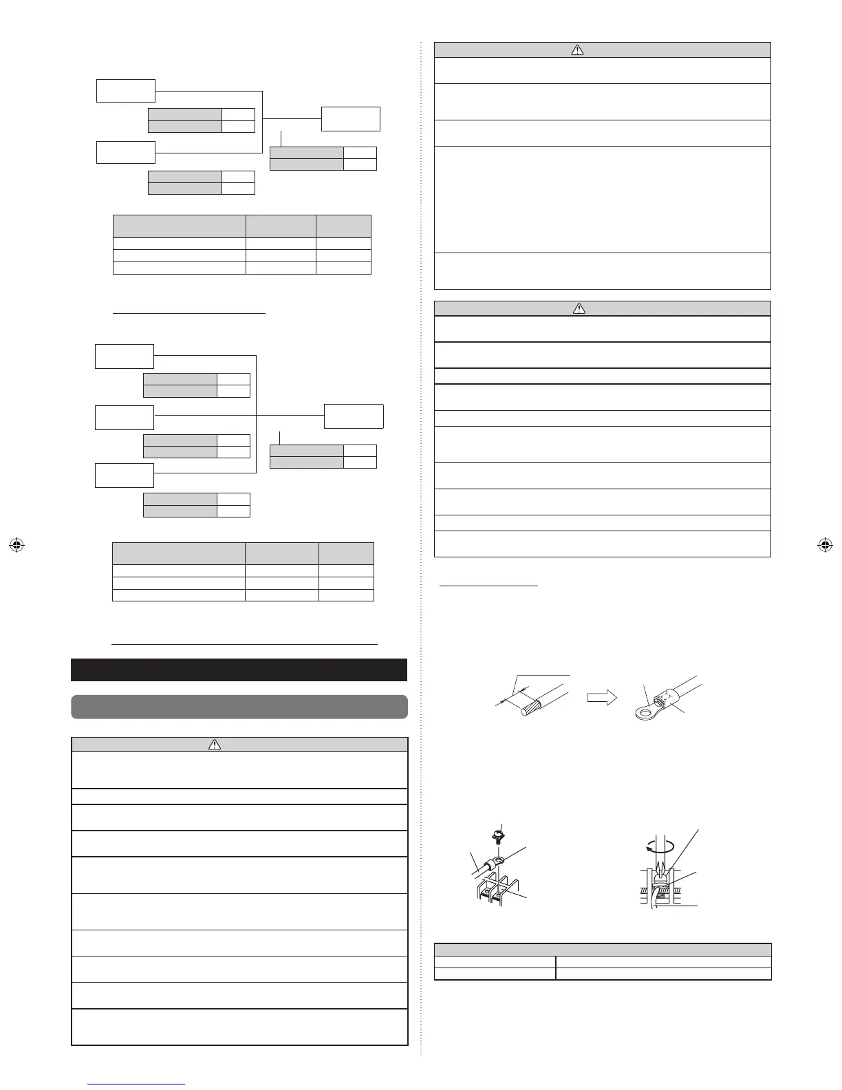
How to connect wiring to the terminal
Caution when wiring cable
When stripping off the coating of a lead wire, always use a special tool such as a wire
stripper. If there is no special tool available, carefully strip the coating with a knife etc.
(1) Use crimp-type terminals with insulating sleeves as shown in the gure below to
connect to the terminal block.
(2) Securely clamp the crimp-type terminals to the wires using an appropriate tool so
that the wires do not come loose.
Sleeve
Strip : 10 mm
Crimp-type
terminal
(3) Use the specied wires, connect them securely, and fasten them so that there is no
stress placed on the terminals.
(4) Use an appropriate screwdriver to tighten the terminal screws. Do not use a
screwdriver that is too small, otherwise, the screw heads may be damaged and
prevent the screws from being properly tightened.
(5) Do not tighten the terminal screws too much, otherwise, the screws may break.
Wire
Screw with special washer
Crimp-type terminal
Terminal blocks
Screw with
special washer
Wire
Crimp-type
terminal
(6) See the table below for the terminal screw tightening torques.
Tightening torque
[N·m (kgf·cm)]
M4 screw 1.2 to 1.8 (12 to 18)
M5 screw 2.0 to 3.0 (20 to 30)
 Loading...