En-3
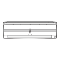
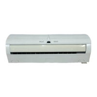
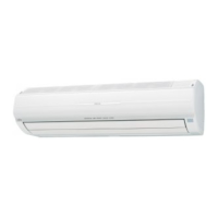
Fig. 1 Indoor Unit
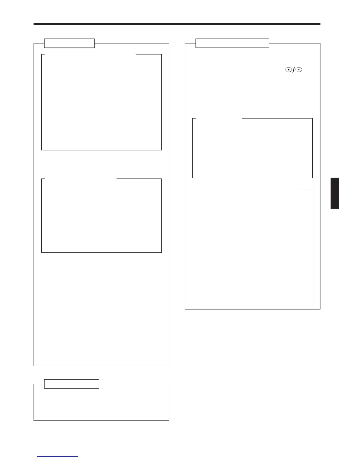
1 Operating Control Panel (Fig. 2)
2 MANUAL AUTO button
This button can be used for temporary opera-
tion in the AUTOMATIC mode in the event the
remote control unit is unavailable.
Press the MANUAL AUTO button
● Fan speed will be set to “AUTO” and the
thermostat will be set for “normal”.
● To stop operation, either press the
MANUAL AUTO button once again, or set
the POWER switch to OFF.
3 POWER switch
ON : Set to this position when using the unit.
OFF : Set to this position when not using the
unit for an extended period of time.
4 Remote Control Signal Receiver (☞ P. 5 )
Signals from the remote control unit are re-
ceived here.
5 Indicator Lamps (Fig. 3)
These indicator lamps show the current oper-
ating status.
6 OPERATION Indicator (red)
● Lights when unit is operating.
● Flashes quickly for about one second when
a signal is received from the remote con-
trol unit.
*● Flashes slowly during defrosting opera-
tion. (☞ P. 17)
7 TIMER Indicator (green)
Lights during TIMER operation.
8 Air Intake Grille
Air is taken in here.
9 Air Filter (☞ P. 14)
Removes all dirt and dust from the air.
0 Air flow-direction Louvers (☞ P. 9 )
Control airflow in the vertical (up-down) direc-
tion.
A Right-left Louvers (☞ P. 10)
(behind Air flow-direction Louvers)
Control airflow in the horizontal (right-left) di-
rection.
B Pipe Unit
* C Power Plug
D Drain Hose
Moisture condensed from the air during Cool-
ing and Drying operations is drained here.
Fig. 4 Outdoor Unit
E Air inlet
(Rear and side panels)
F Air outlet
Warm or cool air is blown out.
Fig. 5 Remote Control Unit
G SLEEP Button (☞ P. 12)
H MASTER CONTROL Button
I SET TEMP./SET TIME Buttons ( )
J Signal Transmitter
K TIMER Button (☞ P. 11 and 12)
L FAN CONTROL Button
M START/STOP Button
N AIR FLOW DIRECTION Button (☞ P. 9 )
Rear side (Fig. 6)
O TIME ADJUST Button (☞ P. 5 )
P ACL Button (☞ P. 4 )
(located inside battery compartment)
This button is used when replacing batteries.
Q TEST RUN Button
This button is used when testing the air con-
ditioner after installation. Do not use under
normal conditions.
R Remote Control Unit Display (Fig. 7)
S Transmit Indicator
T Clock Display
● When CLOCK is displayed, the current time
is shown in 24-hour format (0:00 to 23:59).
● When TIMER is displayed, the timer set-
ting is shown in 24-hour format (0:00 to
23:59).
● When SLEEP timer has been selected, the
display shows the remaining time until the
unit turns off (0H:05M to 9H:55M).
U Operating Mode Display
V Timer Mode Display
W Fan Speed Display
X Temperature Set Display
Y Timer Set Indicator
Z Temperature Set Indicator
 Loading...