En-3
Accessories2. 4.
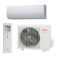
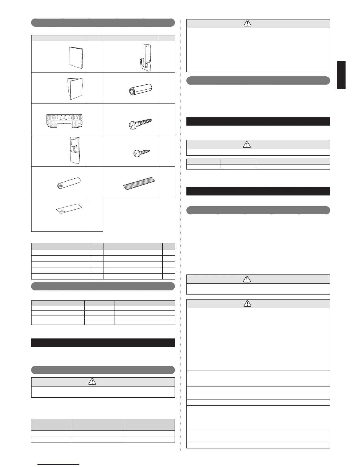
The following installation accessories are supplied. Use them as required.
Name and Shape
Q’ty
Name and Shape
Q’ty
Operating manual
1
Remote controller
holder
1
Installation manual
(This manual)
1
Cloth tape
1
Wall hook bracket
1
Tapping screw
(M4 × 25 mm)
5
Remote controller
1
Tapping screw
(M3 × 12 mm)
2
Battery
2
Air cleaning filter
2
Seal A
It is used when the diameter of
gas pipe is Ø12.70 or more.
It is necessary when using AS14.
1
The following items are necessary to install this air conditioner. (The items are not includ-
ed with the air conditioner and must be purchased separately.)
Name Q’ty Name Q’ty
Connection pipe assembly 1 Wall cap 1
Connection cable (4-conductor)
1 Saddle 1 set
Wall pipe 1 Drain hose 1
Decorative tape 1 Tapping screws 1 set
Vinyl tape 1 Sealant 1
Optional parts2. 5.
Refer to each installation manual for the method of installing optional parts.
Parts name Model No. Application
Wired remote controller * UTY-RNN!M For air conditioner operation
Simple remote controller * UTY-RSN!M For air conditioner operation
External connect kit * UTY-XWZXZ5 For control input/output port
Communication kit UTY-TWBXF For the installation of optional parts
* Optional communication kit is necessary for the installation.
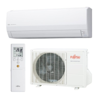
GENERAL SPECIFICATION3.
This installation manual brieß y outlines where and how to install the air conditioning system. Please
read over the entire set of instructions for the indoor and outdoor units and make sure all accessory
parts listed are with the system before beginning.
Type of copper pipe and insulation material3. 1.
CAUTION
Refer to the installation manual for the outdoor unit for description of allowable pipe length
and height difference.
Selecting pipe sizes
The diameters of the connection pipes according to the capacity of the indoor unit.
Refer to the following table for the proper diameters of the connection pipes between the
indoor unit and outdoor unit or branch box.
Capacity of indoor unit
Gas pipe size (thickness)
[mm]
Liquid pipe size (thickness)
[mm]
9, 12 Ø 9.52(0.8) Ø 6.35(0.8)
14 Ø 12.70(0.8) Ø 6.35(0.8)
CAUTION
Install heat insulation around both the gas and liquid pipes. Failure to do so may
cause water leaks.
Use heat insulation with heat resistance above 120 °C. Reverse cycle model only)
In addition, if the humidity level at the installation location of the refrigerant piping is
expected to exceed 70%, install heat insulation around the refrigerant piping. If the
expected humidity level is 70-80%, use heat insulation that is 15 mm or thicker and if
the expected humidity exceeds 80%, use heat insulation that is 20 mm or thicker.
If heat insulation is used that is not as thick as speciÞ ed, condensation may form on the surface
of the insulation.
In addition, use heat insulation with heat conductivity of 0.045 W/(m·K) or less 20 °C.
Additional materials required for installation3. 2.
A. Refrigeration (armored) tape
B. Insulated staples or clamps for connecting wire (See your local electrical codes.)
C. Putty
D. Refrigeration lubricant
E. Clamps or saddles to secure refrigerant piping
ELECTRICAL REQUIREMENT4.
The indoor unit is powered from the outdoor unit or branch box. Do not power indoor unit
from separate power source.
WARNING
Refer to local codes for acceptable cable type.
Cable
Cable size
Remarks
Connection cable
Type 60245 IEC 57
3 cable + Ground, 1 Ø 230 V
Max. Cable Length: Limit voltage drop to less than 2%. Increase cable gauge if voltage
drop is 2% or more.
SELECTING THE MOUNTING POSITION5.
Decide the mounting position with the customer as follows:
Indoor unit5. 1.
(1) Install the indoor unit level on a strong wall which is not subject to vibration.
(2) The inlet and outlet ports should not be obstructed: the air should be able to blow all
over the room.
(3)
Install the unit a dedicated electrical branch circuit.
(4)
Do not install the unit where it will be exposed to direct sunlight.
(5)
Install the unit where connection to the outdoor unit or branch box is easy.
(6) Install the unit where the drain pipe can be easily installed.
(7) Take servicing, etc. into consideration and leave the spaces shown in “6.1. Installation
dimensions”. Also install the unit where the Þ lter can be removed.
Correct initial installation location is important because it is difÞ cult to move unit after it is
installed.
WARNING
Select installation locations that can properly support the weight of the indoor. Install the
units securely so that they do not topple or fall.
CAUTION
Do not install the unit in the following areas:
•
Area with high salt content, such as at the seaside. It will deteriorate metal parts, causing the parts
to fail or the unit to leak water.
•
Area Þ lled with mineral oil or containing a large amount of splashed oil or steam, such as a
kitchen.
It will deteriorate plastic parts, causing the parts to fail or the unit to leak water.
•
Area that generates substances that adversely affect the equipment, such as sulfuric gas, chlorine
gas, acid, or alkali.
It will cause the copper pipes and brazed joints to corrode, which can cause refrigerant leakage.
•
Area that can cause combustible gas to leak, contains suspended carbon Þ bers or ß ammable
dust, or volatile inß ammables such as paint thinner or gasoline.
•
If gas leaks and settles around the unit, it can cause a Þ re.
•
Area where animals may urinate on the unit or ammonia may be generated.
Do not use the unit for special purposes, such as storing food, raising animals, growing
plants, or preserving precision devices or art objects.
It can degrade the quality of the preserved or stored objects.
Do not install where there is the danger of combustible gas leakage.
Do not install the unit near a source of heat, steam, or ß ammable gas.
Install the unit where drainage does not cause any trouble.
Install the indoor unit, outdoor unit, branch box, power supply cable, transmission cable,
and remote control cable at least 1 m away from a television or radio receivers. The
purpose of this is to prevent TV reception interference or radio noise.
(Even if they are installed more than 1 m apart, you could still receive noise under some
signal conditions.)
If children under 10 years old may approach the unit, take preventive measures so that
they cannot reach the unit.
Install the indoor unit on the wall where the height from the ß oors more than 1.8 m.
 Loading...