10
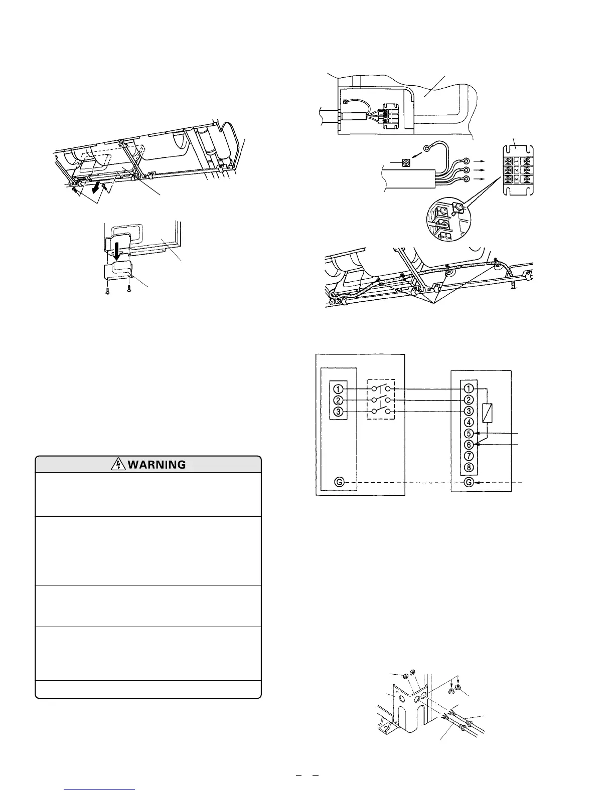
2. OUTDOOR UNIT SIDE
(1) Dismount the plugs on the Cabinet D.
(2) Temporarily mount the conduit tubes on the
Cabinet D.
(3) Properly connect both the power supply and inter-
unit lines to the corresponding terminals on the ter-
minal board.
Refer to the wiring system diagram in Fig. 39.
(4) Ground the unit in accordance with local codes.
(5) Be sure to size each wire allowing several inches
longer than the required length for wiring.
(6) Use lock nuts to secure the conduit tube.
(2) Remove the Cover A and install the Connection
cord. (Figs. 36 and 37)
(3) Reattach Cover A. Then fasten the control box back
into its original position with the two tapping
screws.
(4) Attach the connection cord and cable clips. Make
sure that they are positioned so that they will not
interfere with opening and closing of the intake
grille or with removal and installation of the air fil-
ters. (Fig. 38)
(1) Before starting work, check that
power is not being supplied to the
outdoor unit.
(2) Match the terminal board numbers
and connection cord colors with
those of the outdoor unit.
Erroneous wiring may cause burning
of the electric parts.
(3) Connect the connection cord firmly
to the terminal board. Imperfect
installation may cause a fire.
(4) Always fasten the outside covering
of the connection cord with the cord
clamp. (If the insulator is chafed,
electric leakage may occur.)
(5) Always connect the ground wire.
Fig. 37
Control box
Terminal board
Earth screw
Connection
cord
Cable clip
Fig. 40
Lock nut
Plug
Power supply
inter-unit line
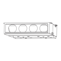
1. INDOOR UNIT SIDE
(1) Remove the two tapping screws and pull the control
box downward. (Fig. 36)
Fig. 36
Indoor unit
Tapping screw
Control box
Control box
Cover A
Fig. 38
Fig. 39
INDOOR
INDOOR UNIT
Terminal
Disconnect
switch
(Field supply)
14WG
(Inter-unit)
Power lines
230/208 V
230/208 V
230/208 V
Grounding
line
OUTDOOR UNIT
Terminal
Fuse
Power supply line
Single-phase, 230/208 V
12AWG (30,000 BTU/h type)
10AWG (36,000 BTU/h type)
 Loading...