Pump Error
CLOGGED THE CIRCULATION
PUMP AND/OR HEATING CIECUIT
check the pump and heating circuit
PUMP
PCB (CONTROLLER) (*1)
P1
low-outside air
temperature limit
THE OUTDOOR TEMP. FALLS
BELOW -20°C
below -20°C, it is likely not to operate for the protection of the
equipment
U5
SENSOR TEMP. OUTDOOR check the resistance by tester [see table 1]
not cool down
not warm up
check the resistance by tester [see table 1]
SENSOR,TEMP. OUTGOING AND
RETURN CIRCULATING WATER
GAS LEAKAGE check the service valve and refrigerant circuit ( pipe )
CLOGGED HEATING CIRCUIT
check temperature dierence heating ow/return [see page 11]
large dierence meens ow rate is too low
SHORT CYCLE
(INSUFFICIENT AIR CIRCULATION)
check the blockage of air inlet & outlet
(*1) When checking fan motor and/or pump, turn o the power supply completely and touch their terminal or connector.
(*2) In case of detecting open circuit of the discharge temperature thermistor, error display appears 10 minutes after start op erating.
In case of detecting short circuit of the discharge temperature thermistor, error display appears immediately.
check the voltage of PUMP [see g. 3]
4-WAY VALVE check the resistance by tester [see g. 4]
APPEARANCE, PORTION, PARTS SEEMED WRONG METHOD OF CHECK
Inverter PCB
serial error
CONNECTOR 13 is RARE CONTACT
or POWER MODULE and
PCB(CONTROLLER)
Turn o the power supply , wait for about 3 minutes
take o and insert the connector 13 , and then power up again
after replacing POWER MODULE, restart operation again
Return circulating
water temp.
sensor Error
SENSOR, TEMP. RETURN
CIRCULATING WATER
check the resistance by tester [see table 1] E5
C8
Outgoing circulating
temp. sensor Error
SENSOR, TEMP. OUTGOING
CIRCULATING WATER
check the resistance by tester [see table 1]E4
Heat pump
regulator PCB
serial error
CC
MIS-WIRING (I/F PCB-HEAT PUMP
REGULATOR) OR RARE CONTACT
check the wiring connection and rare contact
I/F PCB other than described above
other than described above
remove the clog, then restart operation.
When the temperature rises, the unit automatically restarts the operation.
if the sensor is faulty, it should be replaced.
if any of these sensors is faulty, it should be replaced.
after xing the leakage point, collect the refrigerant once, then recharge with
prescribed mass.
remove the clog, then restart operation.
ensure the installation position to avoid blockage of air inlet & outlet.
if the voltage is normal, PUMP should be replaced.
if the voltage is abnormal, PCB(CONTROLLER) should be replaced.
if the value is abnormal, the coil should be replaced.
if the same error code appears, POWER MODULE should be replaced.
if the same error code appears, PCB(CONTROLLER) should be replaced.
if the sensor is faulty, it should be replaced.
if the sensor is faulty, it should be replaced.
check wiring connection and rate contact.
then restart operation.
I/F PCB should be replaced.
HEAT PUMP REGULATOR PCB should be replaced.Heat pump regulator
PCB (CONTROLLER)
FUSE CF4 (250V T3.15A)
FAN MOTOR (*1)
Fan motor
Error
C3
rise of temperature
(above 110°C)
of POWER MODULE
Power module
sensor Error
check the place of installation (blockage of air inlet & outlet)
SENSOR, TEMP. POWER MODULE
MIS-INSTALLATION
C4
C5
C6
I/F PCB serial errorC7
MIS-WIRING [ PCB ( CONTROLLER )
- I/F PCB CONNECTING CABLE ] OR
RARE CONTACT
check the wiring connection and rare contact
other than described aboveI/F PCB
PCB (CONTROLLER)
check the electric continuity FUSE CF4 (250V T3.15A) by tester
other than described above
SENSOR, TEMP. POWER MODULE
PCB (Controller)
Error
PCB (CONTROLLER)
POWER MODULE should be replaced.
ensure the installation position to avoid blockage of air inlet & outlet.
after correcting mis wiring, restart operation.
I/F PCB should be replaced.
if CF4 is blown, FAN MOTOR and CF4 should be replaced.
if CF4 is not blown, check the voltage of FAN MOTOR.[see g 2 ]
if the voltage is normal, FAN MOTOR should be replaced.
if the voltage is faulty, PCB(CONTROLLER) should be replaced.
POWER MODULE should be replaced.
PCB(CONTROLLER) should be replaced.
PCB(CONTROLLER) should be replaced.
Suction temp.
sensor Error
Outdoor temp.
sensor Error
check the resistance by tester [see table 1]
check the resistance by tester [see table 1]
check the resistance by tester [see table 1]
check the resistance by tester [see table 2] (*2)
SENSOR, TEMP. OUTDOOR
SENSOR, TEMP. SUCTION
Defrost temp.
sensor Error
SENSOR, TEMP. DEFROST
Discharge temp.
sensor Error
SENSOR, TEMP. DISCHARGE
A6
A7
A8
C2
Power module
Error
POWER MODULEC0
if the sensor is faulty, it should be replaced.
if the sensor is faulty, it should be replaced.
if the sensor is faulty, it should be replaced.
if the sensor is faulty, it should be replaced.
POWER MODULE should be replaced.
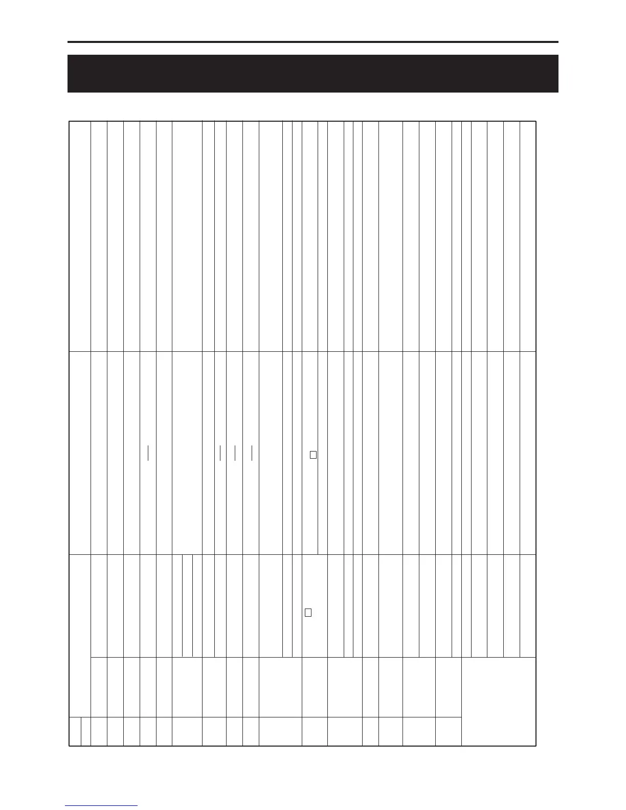
TROUBLESHOOTING
ERROR
CODES
UNIT
 Loading...