23
2.3 Wiring of Power Supply Unit
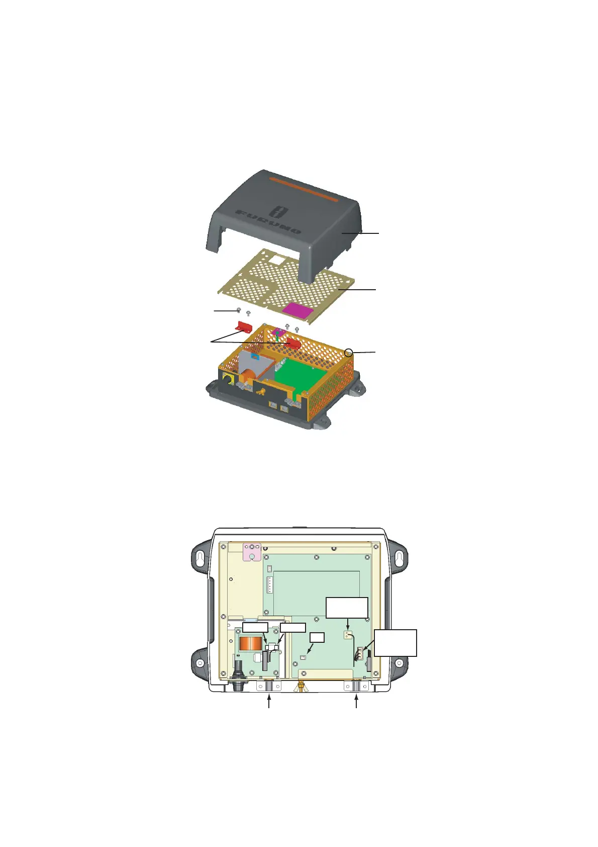
2.3.1 Wiring inside power supply unit PSU-013 (for DRS25A)
1. Detach the body cover by hand.
2. Loosen six pan head screws (M3x8) and slide the shield cover upward to remove it.
3. Unfasten four pan head screws (M14x10) to remove two cable clamps.
4. Connect the VL3P-VV-S2X2C-AA050 and MOD-ASW0002 cables (supplied) to appropriate
connectors in the power supply unit as shown below.
Note: W
hen the power supply unit is connected to TZT9/14/BB, attach the XH
Connector Asembly (supplied with PSU-013) to J7 on the PWR board. For
details, see "How to connect TZT9/14/BB" (supplied with PSU-013).
5. Remove two cable clamps, shield cover and body cover in that order.
6. Connect other cables.
Body cover
Shield cover
Pan head screws
(M3x8, 6 pcs.)
Pan head screws
(M4x10, 4 pcs.)
Cable clamps
VL3P-VV-S2X2C-AA050 cable MOD-ASW0002 cable
(Power)
White
Black
3: Blue
2: Black
1: White
1: Red
2: N. C.
J7
 Loading...