Apollo
™
MS-WB670 Installation Instructions
Important Safety Information
WARNING
Failure to follow these warnings and cautions could result in personal injury,
damage to the vessel, or poor product performance.
See the Important Safety and Product Information guide in the product box for
product warnings and other important information.
This device must be installed according to these instructions.
Disconnect the vessel's power supply before beginning to install this product.
Before applying power to this product, make sure it has been correctly
grounded, following the instructions in the guide.
CAUTION
Always wear safety goggles, ear protection, and a dust mask when drilling,
cutting, or sanding.
NOTICE
When drilling or cutting, always check what is on the opposite side of the
surface.
Do not use the stereo as a template when drilling the mounting holes because
this may damage the glass display and void the warranty. You must only use
the included template to correctly drill the mounting holes.
You must read all installation instructions before beginning the installation. If
you experience difficulty during the installation, contact
FUSION
®
Product
Support.
What's In the Box
• Mounting gasket
• Four 8-gauge, self-tapping screws
• Two screw covers
• Power and speaker wiring harness
• Auxiliary-in, line-out, and subwoofer-out wiring harnesses
• Dust cover
Tools Needed
• Phillips screwdriver
• Electric drill
• Drill bit (size varies based on surface material and screws used)
• Rotary cutting tool or jigsaw
• Silicone-based marine sealant (optional)
Mounting Considerations
CAUTION
In high ambient temperatures and after extended use, the device enclosure
may reach temperatures deemed dangerous to touch. As a result, the unit
must be installed in a location where it cannot be touched during operation.
NOTICE
This device should be mounted in a location that is not exposed to extreme
temperatures or conditions. The temperature range for this device is listed in
the product specifications. Extended exposure to temperatures exceeding the
specified temperature range, in storage or operating conditions, may cause
device failure. Extreme-temperature-induced damage and related
consequences are not covered by the warranty.
When selecting a mounting location for the black box device, observe these
considerations.
•
The device must be mounted in a location where it is not submerged.
• The device must be mounted in a location with adequate ventilation where
it is not exposed to extreme temperatures.
• The device should be mounted so the cables can be connected easily.
• To achieve IPX3 water ingress protection and optimal heat sink cooling,
the device must be mounted on a vertical surface with the connectors
pointing downward.
•
The device can be mounted on a horizontal surface, but such positioning
might not achieve IPX3 water ingress protection.
• To avoid interference with a magnetic compass, the device should be
installed at least 15 cm (5.91 in.) away from a compass.
When selecting a mounting location for the remote control, observe these
considerations.
• The remote control must be mounted in a location where there is at least
70 mm (2.75 in.) of clearance behind the mounting surface and you can
access the controls after it is mounted.
• If you need to mount the remote control outside the cabin, it must be
mounted in a location well above the waterline, where it is not submerged.
• If you need to mount the remote control outside the boat, it should be
mounted in a location where it will not be damaged by a docks, pilings, or
other pieces of equipment.
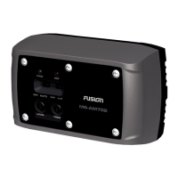
Mounting the Apollo MS-WB670 Black Box Device
NOTICE
If you are mounting the device in fiberglass, when drilling the pilot holes, use a
countersink bit to drill a clearance counterbore through only the top gel-coat
layer. This will help to avoid cracking in the gel-coat layer when the screws are
tightened.
NOTE: Screws are included with the device, but they may not be suitable for
the mounting surface.
Before you mount the device, you must select a mounting location, and
determine what screws and other mounting hardware are needed for the
surface.
1
Place the black box device in the mounting location, and mark the location
of the pilot holes.
2
Drill a pilot hole for one corner of the device.
3
Loosely fasten the device to the mounting surface with one corner, and
examine the other three pilot-hole marks.
4
Mark new pilot-hole locations if necessary, and remove the device from the
mounting surface.
5
Drill the remaining pilot holes.
6
Secure the device to the mounting location.
Connection Considerations
For the stereo to function correctly, you must connect it to power, to speakers,
and to input sources. You should carefully plan the layout of the stereo,
speakers, input sources, optional
NMEA 2000
®
network, and optional FUSION
PartyBus
™
devices or network before making any connections.
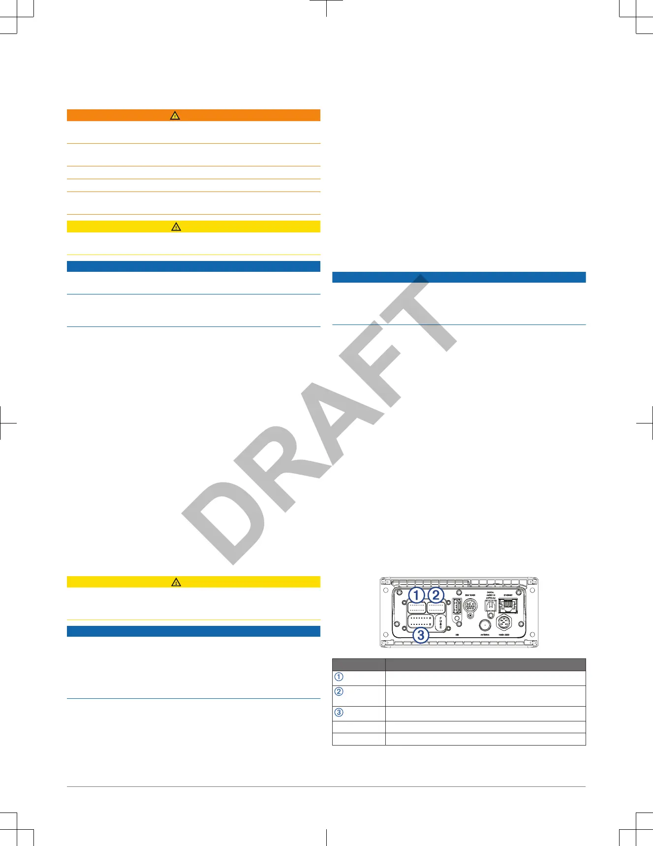
Port Identification
Item Description
Connects the stereo to the wiring harness for zone 3.
Connects the stereo to the wiring harness for auxiliary input 1, and
for the line and subwoofer outputs for zones 1 and 2.
Connects the stereo to the power and speaker wiring harness.
FUSE Contains the 15 A fuse for the device.
USB Connects the stereo to a USB source.
2 Installation Instructions
 Loading...