Item Description
SXM TUNER Connects the stereo to a SiriusXM
®
Connect Tuner to receive
SiriusXM stations where available (not included).
Connects to a FUSION DAB module to receive DAB stations where
available (not included).
DIGITAL AUDIO
IN (OPTICAL)
Connects the stereo to an optical digital audio source, such as TV or
DVD player.
ETHERNET Connects the stereo to another FUSION PartyBus stereo, zone
stereo, or network (FUSION PartyBus Networking, page 5).
ANTENNA Connects the stereo to a typical AM/FM antenna.
If you are installing the stereo on a boat with a metal hull, you must
use a ground-dependent antenna. If you are installing the stereo on
a boat with a non-metal hull, you must use a ground-independent
antenna. See the installation instructions provided with your antenna
for more information.
NMEA 2000 Connects the stereo to a NMEA 2000 network (NMEA 2000 System
Wiring Diagram, page 4).
Connects to an NRX series remote control directly (Configuring an
Optional Wired NRX Remote Control, page 4).
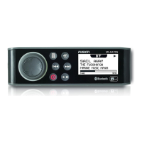
Wiring Harness Wire and Connector Identification
Wire or RCA
Connector Function
Bare Wire
Color or
RCA Label
Name
Notes
Ground (-) Black Connects to the negative terminal of a 12 Vdc
power source capable of supplying 15 A. You
should connect this wire before connecting the
yellow wire. All accessories connected to the
stereo must share a common ground location
(Connecting to Power, page
3).
Power (+) Yellow Connects to the positive terminal of a 12 Vdc
power source capable of supplying 15 A.
Ignition Red Connects to a separately-switched, 12 Vdc
connection, such as an ignition bus, to turn the
stereo on and off. If you are not using a
switched 12 Vdc connection, you must connect
this to the same source as the yellow (power)
wire
Amplifier on Blue Connects to optional external amplifiers,
enabling them to turn on when the stereo turns
on.
Telemute Brown Activates when connected to ground.
For example, when you connect this wire to a
compatible, hands-free mobile kit, the audio
mutes or the input switches to AUX when a call
is received and the kit connects this wire to
ground. You can enable this functionality from
the settings menu.
Dim Orange Connects to the boat's illumination wire to dim
the stereo screen when the lights are on.
The gauge of the illumination wire must be
suitable for the fuse supplying the circuit it is
connected to.
Speaker zone 1 left (+) White
Speaker zone 1 left (-) White/black
Wire or RCA
Connector Function
Bare Wire
Color or
RCA Label
Name
Notes
Speaker zone 1
right (+)
Gray
Speaker zone 1
right (-)
Gray/black
Speaker zone 2 left (+) Green
Speaker zone 2 left (-) Green/black
Speaker zone 2
right (+)
Purple
Speaker zone 2
right (-)
Purple/black
Zone 1 line out (left)
Zone 1 line out (right)
Zone 1 subwoofer out
ZONE 1
ZONE 1
SUB OUT
Provides output to an external amplifier, and is
associated with the volume control for zone 1.
Each subwoofer cable provides a single mono
output to a powered subwoofer or subwoofer
amplifier.
Zone 2 line out (left)
Zone 2 line out (right)
Zone 2 subwoofer out
ZONE 2
ZONE 2
SUB OUT
Provides output to an external amplifier, and is
associated with the volume control for zone 2.
Each subwoofer cable provides a single mono
output to a powered subwoofer or subwoofer
amplifier.
Auxiliary in left
Auxiliary in right
AUX IN Provides an RCA stereo line input for audio
sources, such as a CD or MP3 player.
Zone 3 line out (left)
Zone 3 line out (right)
Zone 3 subwoofer out
ZONE 3 Provides output to an external amplifier, and is
associated with the volume control for zone 3.
Each subwoofer cable provides a single mono
output to a powered subwoofer or subwoofer
amplifier.
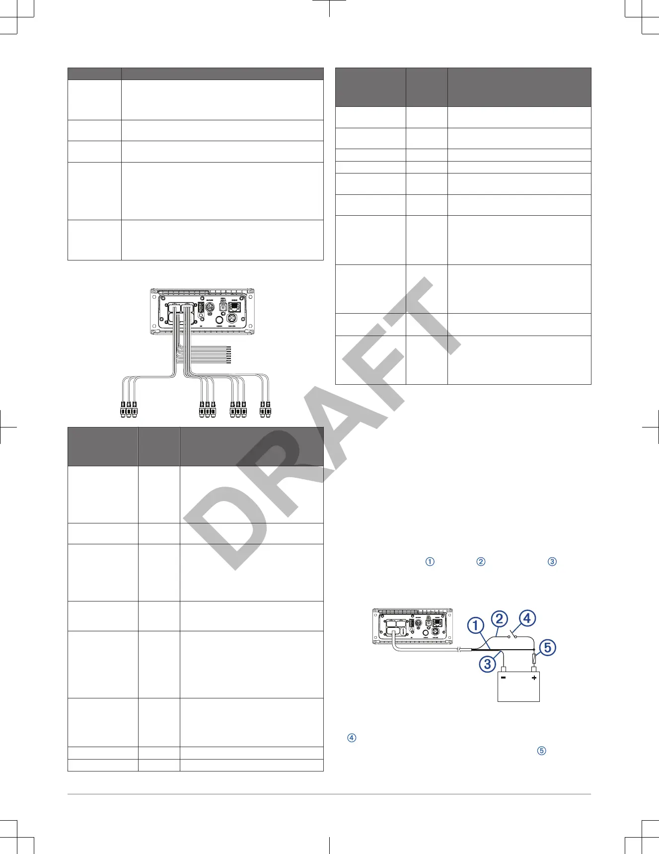
Connecting to Power
When connecting the stereo to power, you must connect both power wires.
You should connect the yellow power wire directly to the battery. This provides
power to the stereo and a constant trickle-power standby feed.
You should connect the red ignition wire to the same battery through the
ignition or another manual switch to turn the stereo on and off. If you are not
routing the red wire through the ignition or another manual switch, you can
connect the red wire to the yellow wire, and connect them both to the positive
(+) battery terminal.
You must connect the power wires to the battery through a 15 A fuse or a 15 A
circuit breaker.
If it is necessary to extend the yellow power and black ground wires, use
14 AWG (2.08 mm
2
) wire. For extensions longer than 1 m (3 ft.), use 12 AWG
(3.31 mm²) wire. If it is necessary to extend the red wire, use 22 AWG
(0.33 mm
2
) wire.
1
Route the yellow power
, red ignition , and black ground wires to
the battery, and route the wiring-harness plug to the stereo.
Do not connect the wiring harness to the stereo until all of the bare wire
connections have been made.
2
Connect the black wire to the negative (-) battery terminal.
3
If you are routing the red wire through the ignition or another manual switch
, connect the red ignition wire to the ignition or switch.
4
Connect the red wire to the yellow wire, install a 15 A fuse as close to
the battery as possible, and connect both wires to the positive (+) battery
terminal.
Installation Instructions 3

 Loading...