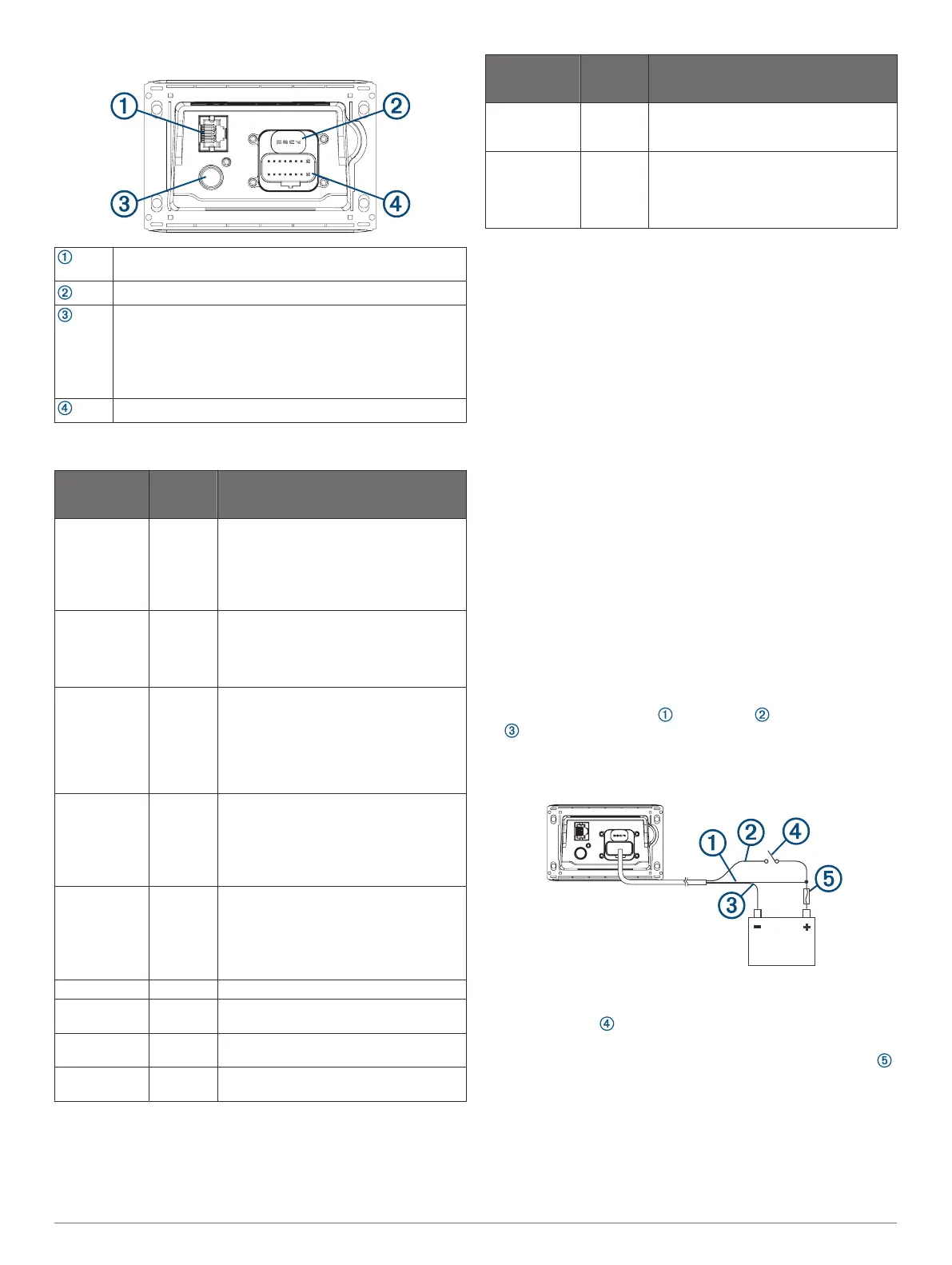
Port Identification
Connects to a Fusion PartyBus stereo or network (Fusion
PartyBus Networking, page 3).
FUSE
Contains the 15 A fuse.
Connects to a typical AM/FM antenna.
If you are installing the stereo on a boat with a metal hull,
you must use a ground-dependent antenna. If you are
installing the stereo on a boat with a non-metal hull, you
must use a ground-independent antenna. See the installation
instructions provided with your antenna for more information.
Connects to the wiring harness
Wiring Harness
Wire Function Wire
Color/
Label
Notes
Ground (-) Black Connects to the negative terminal of a
12 Vdc power source. You should connect
this wire before connecting the yellow
wire. All accessories connected to the
stereo must share a common ground
location.
Power (+) Yellow Connects to the positive terminal of a
12 Vdc power source capable of supplying
15 A. You should fuse this wire as closely
to the power source as possible with a 15
A fuse.
Ignition Red Connects to a separately-switched,
12 Vdc connection, such as an ignition
bus, to turn the stereo on and off. If you
are not using a switched 12 Vdc
connection, you must connect this wire to
the same source as the yellow (power)
wire.
Amplifier on Blue Connects to an optional external amplifier
to turn on he amplifier when the stereo
turns on.
A connected amplifier must use the same
ground (-) as the stereo for this signal wire
to function correctly.
Dim Orange Connects to the boat's illumination wire to
dim the stereo screen when the boat's
lights are on.
The gauge of the illumination wire must be
suitable for the fuse supplying the circuit it
is connected to.
Speaker left (+) White
Speaker left (-) White/
black
Speaker right
(+)
Gray
Speaker right
(-)
Gray/black
Wire Function Wire
Color/
Label
Notes
Line out (left)
Line out (right)
ZONE 1
LINE OUT
Provides output to an external amplifier,
and is associated with the volume control
for zone 1.
Subwoofer out SUB OUT Provides a single, mono output to a
powered subwoofer or subwoofer
amplifier. A connected subwoofer is
associated with the volume control for
zone 1.
Connecting to Power
When connecting the stereo to power, you must connect both
power wires. The yellow power wire must connect to the battery
to provide sufficient power to the stereo. The red ignition should
be connected through the ignition or another manual switch to
enable on/off control of the stereo. This installation method
provides the best performance because the yellow wire retains a
constant trickle-power draw that optimizes the startup time for
the stereo.
NOTE: If you will be storing the vessel for an extended period of
time, you should consider connecting the yellow wire through a
breaker or similar switch, so you can disconnect the trickle-
power draw from the yellow wire and avoid draining the battery
during storage.
If you do not have the option of, or prefer not to use the ignition
to turn the stereo on and off, you can connect the red wire and
the yellow wire to the same switch on an electrical panel. This
installation method results in a slightly longer startup time for the
stereo, but it will not draw power from the battery when the
stereo is turned off using the switch.
You must connect the power wires to the battery through a 15 A
fuse or a 15 A circuit breaker.
If it is necessary to extend the yellow power and black ground
wires, use 14 AWG (2.08 mm
2
) wire. For extensions longer than
1 m (3 ft.), use 12 AWG (3.31 mm²) wire.
If it is necessary to extend the red ignition wire, use 22 AWG
(0.33 mm
2
) wire.
1
Route the yellow power , red ignition , and black ground
wires to the battery, and route the wiring-harness plug to
the stereo.
Do not connect the wiring harness to the stereo until all of the
bare wire connections have been made.
2
Connect the black wire to the negative (-) battery terminal.
3
If you are routing the red wire through the ignition or another
manual switch , connect the red ignition wire to the ignition
or switch.
4
Connect the red wire to the yellow wire, install a 15 A fuse
as close to the battery as possible, and connect both wires to
the positive (+) battery terminal.
NOTE: If you are running the red wire through a fused switch,
it is not necessary to connect the red wire to the yellow wire
or to add an additional fuse to the red wire.
If you connect both the red and yellow wires through a 15 A
circuit breaker, it is not necessary to add an additional fuse.
2 Apollo SRX400 Installation Instructions

 Loading...