).34!,,!4)/.
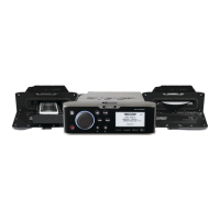
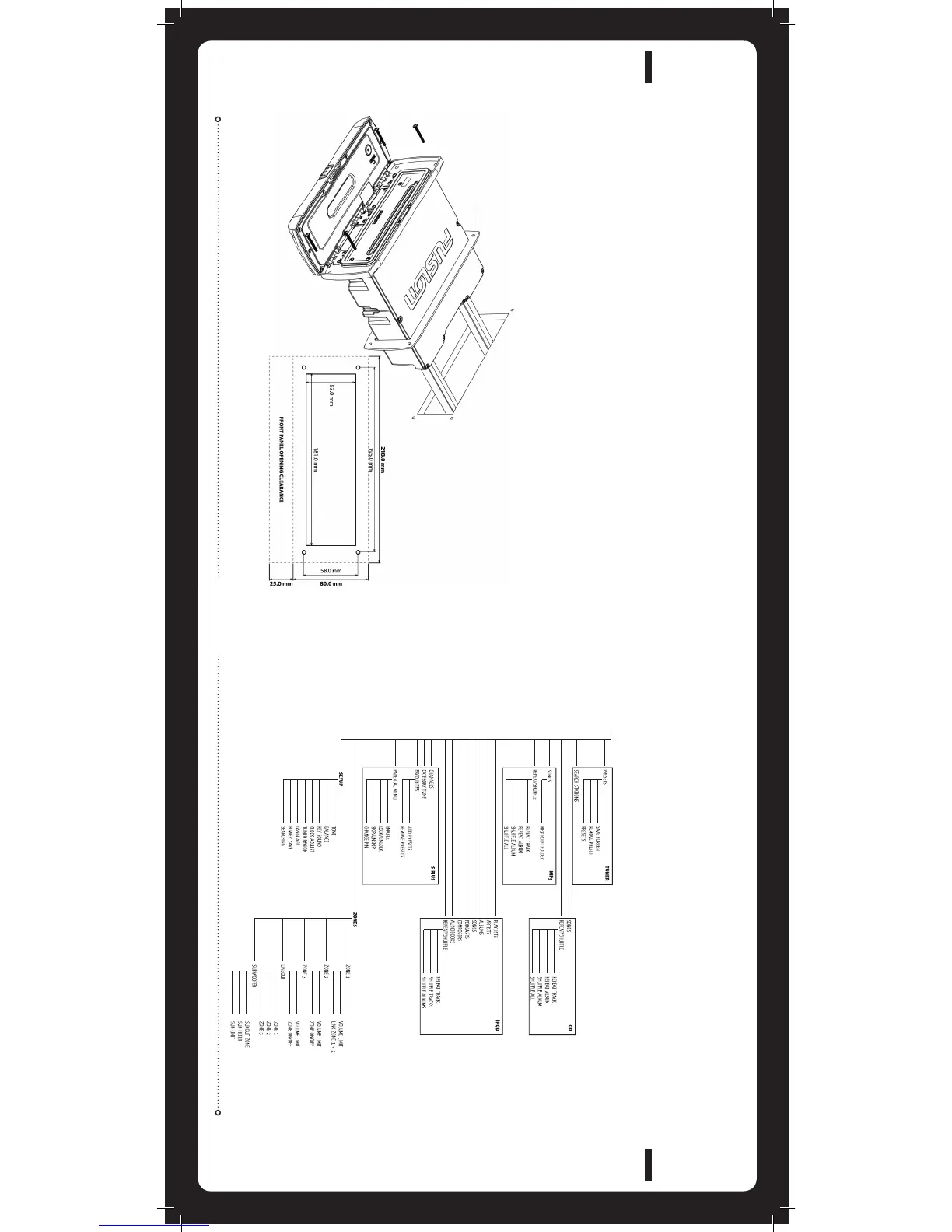
Remove the Sun Cover from the unit
Fit mounting gasket
Insert the unit into the mounting hole
Pull down the front face to expose the mounting screw locations.
»
»
»
»
)&!.9-/$)&)#!4)/.4/4(%6%33%,)32%15)2%$35#(!3$2),,).'(/,%3%4#&53)/.
2%#/--%.$3#/.35,4!4)/.7)4(9/52"/!4$%!,%2/2-!.5&!#452%2"%&/2%(!.$
Use either the supplied 4 x wood screws, or 4 x machined screws
and metal clamps to affix the unit into position.
The unit must be mounted within 30 degrees of the horizontal plane.
»
»
INSTALLATION
MENU STRUCTURE
2//4-%.5
-%.53425#452%
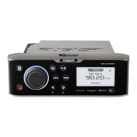
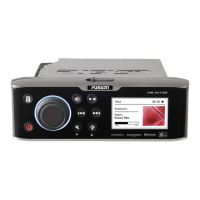
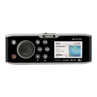
Caution: The MS-IP600, MS-CD600 and MS-AV600 are designed for vessels with a 12V DC Negative ground electrical system
%,%#42)#!,7)2).'
Mounting Gasket
Note: In some circumstances a back strap or
brace may be required at the rear of the Unit
(Back Strap / brace is not included).
Appropriate mounting is very important to
ensure correct operation. Select a location
that allows both free/open airflow around
rear of chassis, whilst minimizing exposure
to moisture. Allow adequate room at the rear
of the unit for the cable looms (approx 2-3”).
 Loading...