system
sets
with
a
receiver
with
shared
power supply
regulator.
The
mark is displayed on the front of the receiver of BEC
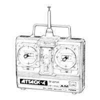
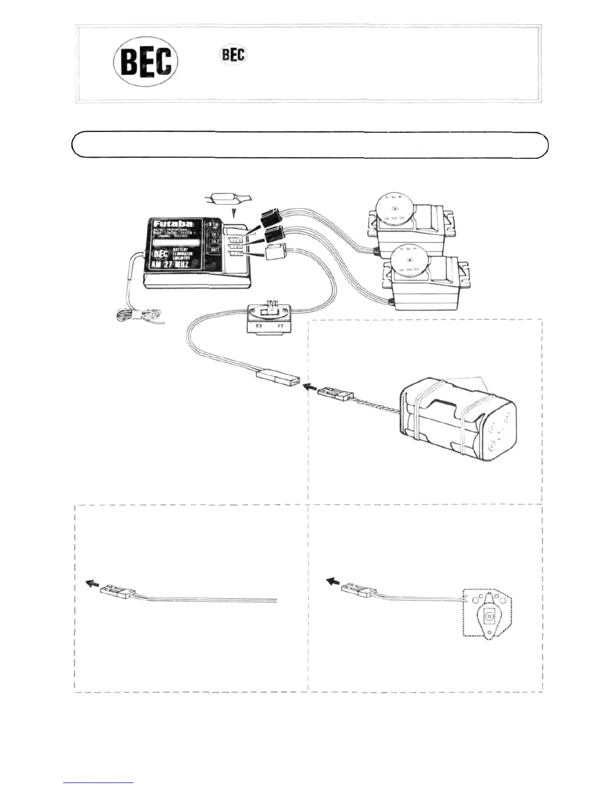
RECEIVER FP-R102GF AND SERVO FP-S128
The Futaba BEC system and BEC & ASP system can also use a common power supply with the conventional four
penlight batteries system (separate power supply).
5
(75MHz-OPTIONAL)
(3) When
motor
car
uses
an
ordi-
nary common power supply
chassis
Red common 2P
connector
(Female pins)
Buy the red common 2P
connector from the kit
manufacturer and connect to
the controller.
Pin 1: Minus
Pin 2: Plus
(2) When motor car uses a speci-
al BEC system chassis (com-
mon power supply specifi-
cations)
Connect to the red common
2P connector of the control-
ler.
Receiver crystal
Steering servo
Throttle servo
Receiver FP-R102GF
ON
OFF
Switch
Antenna wire
Red common 2P
connector (male pins)
Connect the servo and switch as
shown in the figure and extend
the transmitter and receiver ante-
nna
fully.
(Female pins)
Red common
2P
connector
Connection to this connector
(1) When chassis power supply of
engine or motor car is separate
Wrapped with
rubber bands.
(Female pins)
Controller
Red common 2P
connector
 Loading...