Page 3-4 GPS 155XL/GNC300 XL Installation Manual
Revision F 190-00067-22
3.7 CABLE INSTALLATION
1. Route the coaxial cable to the rack location keeping in mind the recommendations of Section 2.
Secure the cable in accordance with good mechanical practices.
2. Trim the coaxial cable to the desired length and install the BNC connector (330-0087-00) per
the cabling instructions in Figure 3-1. If the connector is provided by the installer, follow the
connector manufacturer's instructions for cable preparation.
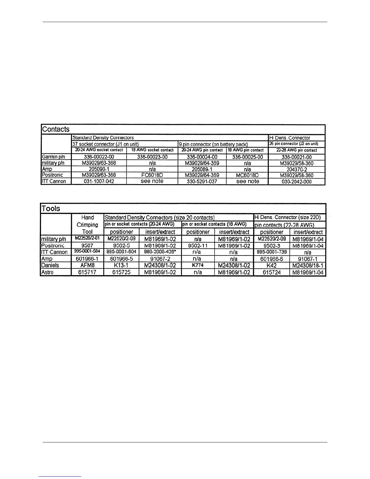
3. Contacts for the 37 and 26 pin connectors must be crimped into the individual wires of the
aircraft wiring harness.
Table 3-1 lists contact part numbers (for reference) and crimp tools.
Table 3-1. Contact Part Numbers and Recommended Crimp Tools
Notes regarding the table:
1. Insert/Extract tools from ITT Cannon are all plastic, others are plastic with metal tip.
2. Non-Garmin part numbers shown are not maintained by Garmin and consequently are subject to change
without notice.
3. Alternate contacts for 18 AWG wire: As an alternate to the Positronic contacts listed (and provided in the
install kit), the installer may use contacts made by ITT Cannon as follows:
• Socket Contact - ITT Cannon P/N 031-10007-001
• Pin Contact - ITT Cannon P/N 330-5291-055. (These contacts require the use of a different crimp
tool positioner than shown in the table, with the part numbers as follows: Daniels P/N K250,
Astro P/N 616245, or ITT Cannon P/N: 980-00005-722.)
 Loading...