190-00906-00 GTX 33 Installation Manual
Rev. F Page 2-3
2.2.2 Additional Equipment Required
The following installation accessories are required but not provided:
• Cables – The installer will supply all system cables including circuit breakers. Cable requirements
and fabrication is detailed in Section 3 of this manual.
• Hardware – #6-32 x 100° Flathead SS Screw [(MS24693, AN507R or other approved fastener)
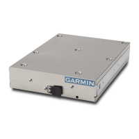
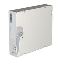
(4 ea.)] for horizontal mounting of the remote stand-alone rack.
• Hardware – #8-32 Panhead Machine Screw [(MS35206, AN526 or other approved fastener)
(4 ea.)] for vertical mounting of the remote stand-alone rack for GTX 33 and GTX 33D.
• Hardware – #8 x 100° Flathead Machine Screw [(see install drawing in Appendix C for more
detail) (4 ea.)] for mounting of the remote stand-alone rack for GTX 33H and GTX 33DH.
• Encoding Altitude Digitizer – For GNS 480 (CNX80), GTN 6XX/7XX, and GMX 200 (MX20)
installation. Use encoding altimeter manufacturer’s instructions. The Garmin GAE 43 (Garmin
P/N 013-00066-00) can provide altitude data in either serial or parallel gray code format.
2.3 Installation Considerations
In a Garmin Integrated Flight Deck, the GTX 33 interfaces with both GIA units. Optional available
discrete line interfaces are shown in Section 4.5 Discrete Functions.
2.3.1 Preservation of Previous Systems
It is the installer’s responsibility to preserve the essential characteristic of the aircraft being modified with
this equipment to be in accordance with the aircraft manufacturer’s original design. This includes the
preservation of multiple power buses, which reduces the probability of interrupting power to essential
instruments and avionics.
 Loading...