42 489 GENERATOR MANAGEMENT RELAY – COMMUNICATIONS GUIDE
CG.3.8 Memory Map Data Formats
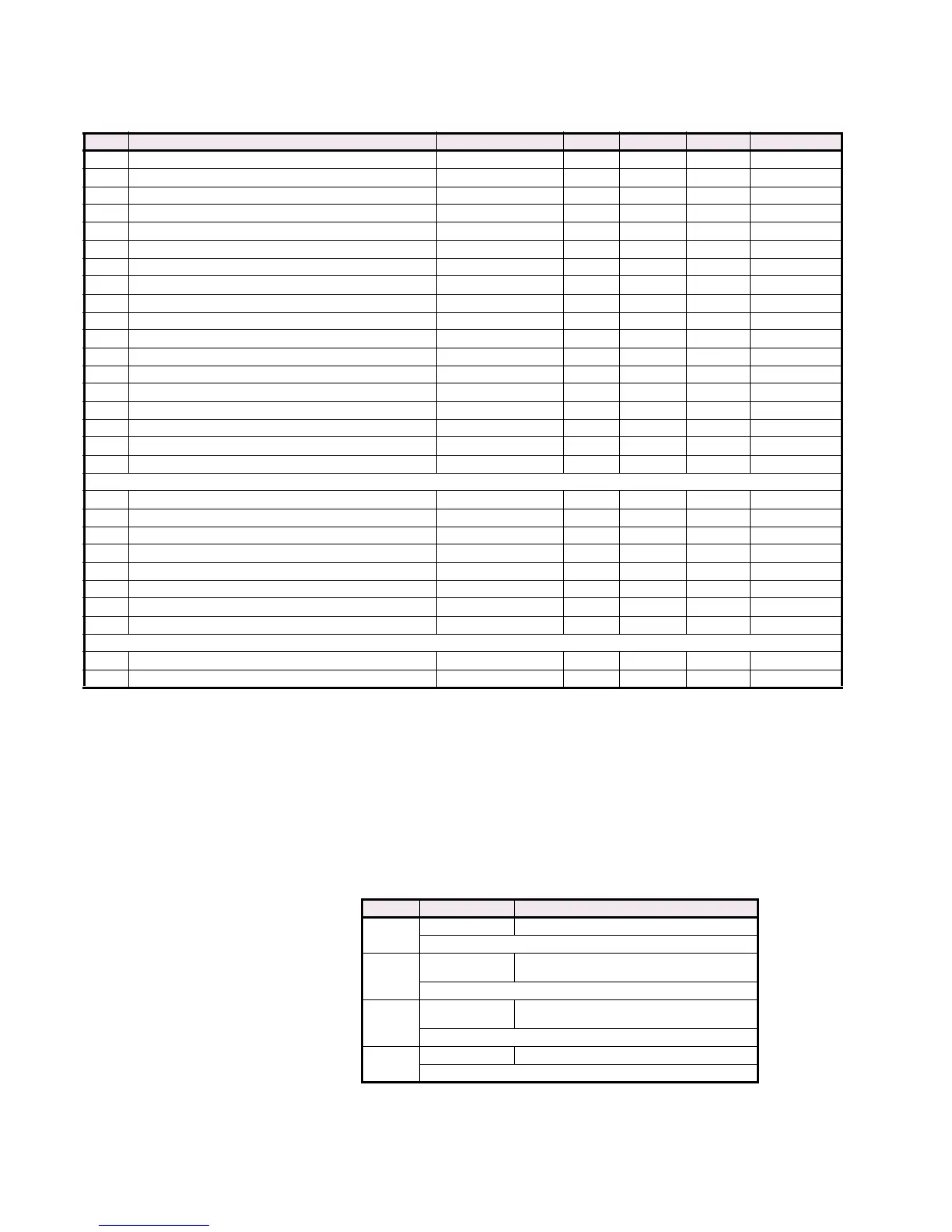
The data formats used in the Modbus memory map are shown below.
302A Hottest Other RTD Temperature –50 to 250 1 °C F4 0
302B Hottest Ambient RTD Number 1 to 12 1 – F1 1
302C Hottest Ambient RTD Temperature –50 to 250 1 °C F4 0
302D Analog Input 1 –50000 to 50000 1 Units F12 0
302F Analog Input 2 –50000 to 50000 1 Units F12 0
3031 Analog Input 3 –50000 to 50000 1 Units F12 0
3033 Analog Input 4 –50000 to 50000 1 Units F12 0
3035 Phase A Neutral Current 0 to 999999 1 Amps F12 0
3037 Phase B Neutral Current 0 to 999999 1 Amps F12 0
3039 Phase C Neutral Current 0 to 999999 1 Amps F12 0
30E0 Hottest Stator RTD Temperature –50 to 250 1 °F F4 0
30E1 Hottest Bearing RTD Temperature –50 to 250 1 °F F4 0
30E2 Hottest Other RTD Temperature –50 to 250 1 °F F4 0
30E3 Hottest Ambient RTD Temperature –50 to 250 1 °F F4 0
30E5 Neutral Voltage (Fundamental) 0 to 250000 1 Volts F10 0
30E7 Neutral Voltage (3rd Harmonic) 0 to 250000 1 Volts F10 0
30E9 Vab/Iab 0 to 65535 1 ohms s F1 0
30EA Vab/Iab Angle 0 to 359 1 ° F1 0
WAVEFORM MEMORY SETUP
30F0 Waveform Memory Trigger Date N/A N/A N/A F18 N/A
30F2 Waveform Memory Trigger Time N/A N/A N/A F19 N/A
30F4 Frequency During Trace Acquisition 0 to 12000 1 Hz F3 0
30F5 Waveform Memory Channel Selector (Holding Register) 0 to 9 1 N/A F214 0
30F6 Waveform Trigger Selector 1 to 65535 1 N/A F1 0
30F7 Waveform Trigger Cause (Read-only) 0 to 139 1 N/A F134 0
30F8 Number of Samples per Trace 1 to 1536 - - F1 N/A
30F9 Number of Waveform Captures Taken 0 to 65535 1 N/A F1 0
WAVEFORM MEMORY SAMPLES
3100 First Waveform Memory Sample –32767 to 32767 1 - F4 0
3700 Last Waveform Memory Sample –32767 to 32767 1 - F4 0
*. A Value of 65535 indicates ‘Never’
. A value of 0xFFFF indicates “no measurable value”.
. Maximum value turns feature ‘Off’
Table CG–1: 489 Memory Map (Sheet 30 of 30)
ADDR Name RANGE STEP UNITS FORMAT DEFAULT
1, 2, 3 See Table footnotes on page page 42
Table CG–2: Data Formats (Sheet 1 of 14)
CODE TYPE DEFINITION
F1
16 bits UNSIGNED VALUE
Example: 1234 stored as 1234
F2
16 bits
UNSIGNED VALUE,
1 DECIMAL PLACE
Example: 123.4 stored as 1234
F3
16 bits
UNSIGNED VALUE,
2 DECIMAL PLACES
Example: 12.34 stored as 1234
F4
16 bits 2’s COMPLEMENT SIGNED VALUE
Example: –1234 stored as –1234 (i.e. 64302)
 Loading...


