DEH40151
DEH40151 Rev.No.02
2
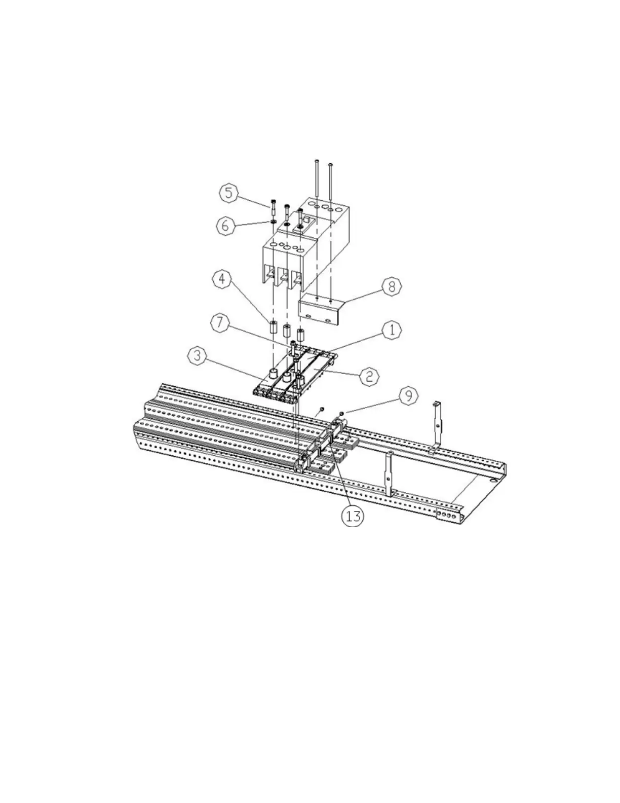
B phase [1] branch base to B phase main busbar but adjacent to A phase branch
base and C phase [3] branch base to C phase main busbar but adjacent to B phase
branch base as shown in fig. 1. All phase branch bases [1],[2] and [3] should be
clamped with main bus using screws[7] with 60 in-lb. Maximum.
Figure 1. Installation of a SF circuit breaker kit on left side of interior, catalog number
ASPP6SF3S, into an A-Series
®
II Panelboards.
5. Refer fig. no.2 to mount the breaker on left side of interior. Place branch base for
A phase[2] adjacent to cross bar[13] as shown in fig.1 and insert the screw [7]
through slot provided for A phase to clamp it with main busbar. Similarly mount
B phase [1] branch busbar to B phase main busbar but adjacent to A phase branch
base and C phase [3] branch busbar to C phase main busbar but adjacent to B
phase branch base as shown in fig. 2. All phase branch bases [1],[2] and [3]
should be clamped with main bus using screws[7] with 50-70 in-lb.
 Loading...