MANUAL
CLOSING
AK-16/26 manually operated
breakers
are
closed by turning the handle
90
degrees
counterclockwise and then clockwise
90
degrees back to the original position. The
initial counterclockWise movement resets
the closing mechanism. The clockwise
movement closes the breaker.
'!'he closing mechanism
of
the
AK~2/3
60/76/100 manual
breakers
is
a
spring
charged mechanism
~imilar
to the
one
used
on AK-2/3-50/76/.100 electrically op-
erated
breakers,
AK-2/3-50/75/100 manual
breakers
are
closed
by
rotating the closing
handle counterclockwise through approxi-
mately 120 degrees, and then clockwise
back through
120
degrees to·
the
normal
handle position. Four such complete move-
ments
of
the handle
are
required to close
the
breaker.
During the four
counterclock~
wise movements and the
first
three clock-
wise movements
of
the handle, the springs
are
charged. After approximately 70
de
..
grees
travel
of
the fourth clockwise handle
movement, the spring ·charged mechanism
is
driven over
...
center
ttµd
the
breaker
closes. A charge
..
indioator, numbered 1 to
4, viewed through the breaker front
esA
cutcheon, moves with each complete handle
movement and indicates the number of
complete handle movements that have been
performed.
AK-4/5R50 manual brealters
are
also
closed
by
means
of
energy released through
the discharge of a closing spring. The
charging
of
the spring
is
done by a single
stroke
of
the brealcer handle. This involves
raising the handle counter.clqckwise from
the vertical position until
a·
stop
is
en
..
countered after about 140 degrees
of
rota-
tion. The spring
is
then extended to
its
fully charged position
as
the handle is
re-
turned to
its
normal vertical position,
Release of the spring, and resultant closina
of
the
breaker,
occurs when the
11
closel'l
button in the escutcheon
is
pushed.
(The
breaker
will close onlr if the racking
mech~
anism
is
in the
"CONN'
or
11
TEST
11
position.)
ELECTRICAL
CLOSING
(Figures 6 and
7)
STANDARD
BREAKERS
AK~15
and AK-25 electrically onerated
REMOTlt-hJ
Cl..OOIMO
OL.OSE
-
1
=
SWITCH
y
t:
~~
~
O>
L
___
6h
vj:~,~
'I
x
-
COIL
L.EGENO
J1.
• X
RELAY
COIL
1J
•
){
REL.A'(
CONTAOT
::t~
• Y
REI.AV
COIL
.If
u Y
RELAY
O.ONTAOT
t"il·bb •
MEOHANIOALLY
OPERATED
&WITOH!8
:f
•NORMALLY
OPEN
SWITCH
OON'fAOT8
* .
NORMALLY
OLOMD
swtrOtt
OONTAOTG
Fig,
6
Simplified
Elementary
Diagram
In-te~'nal
Wiring
AK-15
and 25
Installation and Operation
of
Type
AK
Power Circuit
Breakers
GEK-'7302
OPERATION
breakers
are
closed
by
a solenotdcoll. The
armature
of
the solenoid
is
llnk.ed
to
the
breaker mechanism and tta movement,
operating through
t_he
mechanism, closes
the breaker. The closing Solenoid circuit
may be operated
by
a push button closing
switch
on
the breaker
or
by
a remote
switch
or
relay, depending
on
the individual
arrangements desired.
When
a closing
signal
ts
given, the X relay coil
ts
ener-
gized.and tt
in
turn closes
its
contacts.
One
of
these
seals
in
the X coil circuit; the
other three, which
are
arranged in
series,
energize the solenoid closing coil.
As
the
breaker closes, a mechanically operated
switch opens one
pair
of
its
contacts
(bb)
and. closes another (aa). The contacts
which
Opeh
cut out the X relay
coU.
The
contacts which close
~.nergize
the Y rela,y
coll, whose contacts
now
seal
in the Y coil
and hold open.the X relay coll circuit. This
prevents another closing ope1·ation
if
one
of
the protective ·devices·
ope"rateS
to trtp
the breaker before contact
at
the closing
switch
ls
released,
Large
AK
breakers
(AK-50/75/100)
are
closed
by
the discharge
of
a closing
spring, This rotates a crankshaft which,
by
means
of
an attached
roller,
operates
a closing cam, forcing the movable breaker
contacts against the .stationary contacts.
1'he
closing spring
is
charged through the
operation
of
a motor and gear reduction
unit.
The electrical control system
ts
com-
prised
of
an X relay,
two
double contact
mechanically operated switches (F and
G),
a push button closing switch and
any
means
for remote closing which the
user
may
incorporate into the system.
When
voltage
is
first
applied to the
breaker,
(before
any
closing signal
is
given) the motor
is
ener~
gized through
two
of
the X relay contacts
and the
two
G switch contacts. The motor
tl1en
compresses the closing springs
to
the
"pre~charged"
position
at
which point the
mechanically operated F and G switches
are
operated. Thia opens the G contacts,
stopping the motor, and closes the F con
..
tacts, which readies the system for the
actual closing
of
the breaker,
When
the
push button
or
remote switch signals for
a closing operation, the X relay coli is
"'T
,,
fl1
i~~~~tf
:
'
--lt--J
""
~~
'
REMOTE
_____t-:
01.0SF.
oo
,,
o>
-L
J__
~
x
LEGEND
@ •
OLOSING
MOTOR
ll
e
RELAY
COIL
,,, •
RELAY
OONTAOT
F&G •
MEOHANIOALLY
OPERATED
SWITGtlES
+ •
NORMALLY
OPEN
SWITOff
OONTAOTS
JI'>
•
NORMAL.LY
CLOSEO
SWITCH
OOHTA01S
L •
AUXILIARY
SWITCH
CONTACT
I•'ig. 7
Simplifiea
]gltimentary
D1.agrum
In·ternal
Wiring
AK~50
1
75
and
100
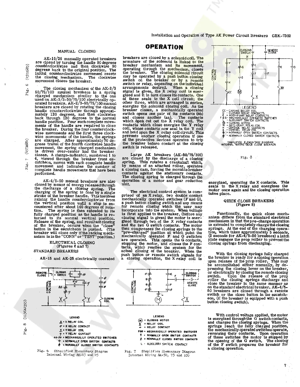
l~ig.
8
energized, operating the
:X
contacts. This
seals
in the X
relay
and energizes tho
motor once again and the closing operation
takes place.
QUICK
CLOSE BREAKERS
(Figure
8)
Functionally, tho quick close
me
ch
..
anism differs from the standard electrical
mechanism in that
thepre
..
chargeoperation
ia extended
to
completely
cha1•ge
the closing
springs.
At
the end
of
the charging opera
..
tion, which takes apP,roximately 5 seconda,
(2
seconds
for
AK-4/6·50
breakers)
a latch
plate engages the prop
roller
to prevent the
closing springs from discharging.
With the closing springs fully charged
the breaker
is
ready for a closing operation
upon release
of
the prop,
roller.
Thia
may
be accomplished
either
manually
1
by de··
pressing the closing
lever
on the oreaker,
or
electrically
by
closing the remote closing
switch,
Upon
the
release
of
the prop
roller
the closing springs discharge and
close the breaker
h1
the same manner
as
on the standard electrical
breaker.
AK
..
4/5
..
50
breakers
are
closed through a remote
switch
or
the close button in the escutch-
eon,
(if
the breaker
is
equipped
With
a push
button closing switch),
With control voltage applied, the motor
is
energized through the G switch contacts,
and charges the closing springs.
When
the
springs reach the fully charged position,
the mechanically operated switches operate,
reversing their contacts.
Upon
operation
of
these switches the motor
ts
stopped by
the opening
of
the G switch, The closing
of
the F switch
prepares
the breaker for
~
closing operation.
7
Courtesy of NationalSwitchgear.com

 Loading...


