28-9266-70 AA Sightglass cover assembly instruction
GE Healthcare
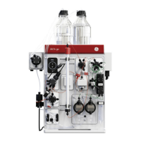
ÄKTAprocess™ Air Trap sightglass cover
Air traps with part numbers listed in the table at the end of this document must be fitted with a metal cover for added protection in case the
air trap is subjected to a sudden overpressure.
Follow the instructions in this document to mount the cover assembly correctly on the air trap.
Note: For added protection, replace all the sightglass mounting bolts with the enclosed 20 mm bolts as instructed below, before mounting the
sightglass cover assembly.
Note: After the sightglass cover assembly is mounted, the air trap should be tested for leakage and/or damage by applying an overpressure of
1.43 times the rated maximum pressure. This test shall be performed with the air trap filled with liquid. Inspect the air trap for any sign of
deformation before the system is taken into operation.
Sightglass cover assembly kit - parts list
Note: There are different variants of the mounting details and supports connecting the air trap to the ÄKTAprocess system frame. You may find
that the illustrations below do not exactly correspond to the mounting details on your specific system. Please contact GE Healthcare
service if you need advice or assistance when mounting the sightglass cover.
Assembly mount procedure - adjust the sightglass assemblies
Part No. of pcs Part number
Sightglass cover – for 6 mm and 0.5 inch air traps 2 28-9260-08
Sightglass cover – for 1 inch air traps 2 28-9260-36
Bolt M6S M6X14 2 28-9260-71
Nut M6M M6 2 59-1582-00
Washer DIN 125 6.4x12x1.6 4 59-0762-00
Bolt MC6S M5x20 12 56-2210-00
Align and tighten the sightglass assemblies
• Remove one of the original bolts (E) from the top sightglass
assembly.
• Move the washer (F) from the original bolt to one of the
replacement bolts enclosed with the cover assembly kit.
Note: It is important that the new, longer bolts are used.
• Insert the replacement bolt through the sightglass bracket
(A) and tighten the first turns carefully by hand. Ensure that
the bolt is positioned straight.
• Repeat the steps above for the other bolts, cross-wise.
• Ensure that the sightglass assembly fits snugly against the
O-ring (D) in the air trap housing and that the
polypropylene spacer (B) and sightglass C are properly
aligned.
• Using a torque setting of 0.5 Nm, tighten the bolts cross-
wise, slowly and carefully.
• Verify that the sightglass bracket (A) is properly aligned
with the air trap housing.
• Increase the torque setting to 1 Nm and tighten the bolts
cross-wise.
Note: To avoid damage to the threads, it is important that the
procedure above is followed, with proper torque settings.