2
28-9266-70 AA Sightglass cover assembly instruction
Assembly mount procedure – 6 mm and 1/2 inch air traps
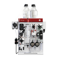
1 Disconnect the air trap and remove the bottom nuts
• Remove the TC coupling (A) and evacuation hose from the
top valve.
• Unscrew and disconnect the cable contacts (B) from the
level sensors.
• Disconnect the air trap inlet and outlet from the system
valves.
• Loosen and remove four bottom nuts (E) and washers from
the connecting rods that are fixed to the support (D).
Note: The nut on the fifth connecting rod does not need to be
removed.
Note: The washers from the two front connecting rods will not
be used when the cover is mounted.
• Lift the air trap from the support (D) and move it to a
suitable place to mount the cover assembly.
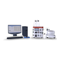
2 Pull out the connecting rods
• Remove the bottom nuts (C) from the two front connecting
rods.
• Pull the connecting rods (F) out of the air trap. Remove the
washers from the rods.
Note: Do not remove the dome nuts. Ensure that the dome nuts
still are securely fastened. If loose, the nuts should be
fastened and locked into place using Loctite™ 243.
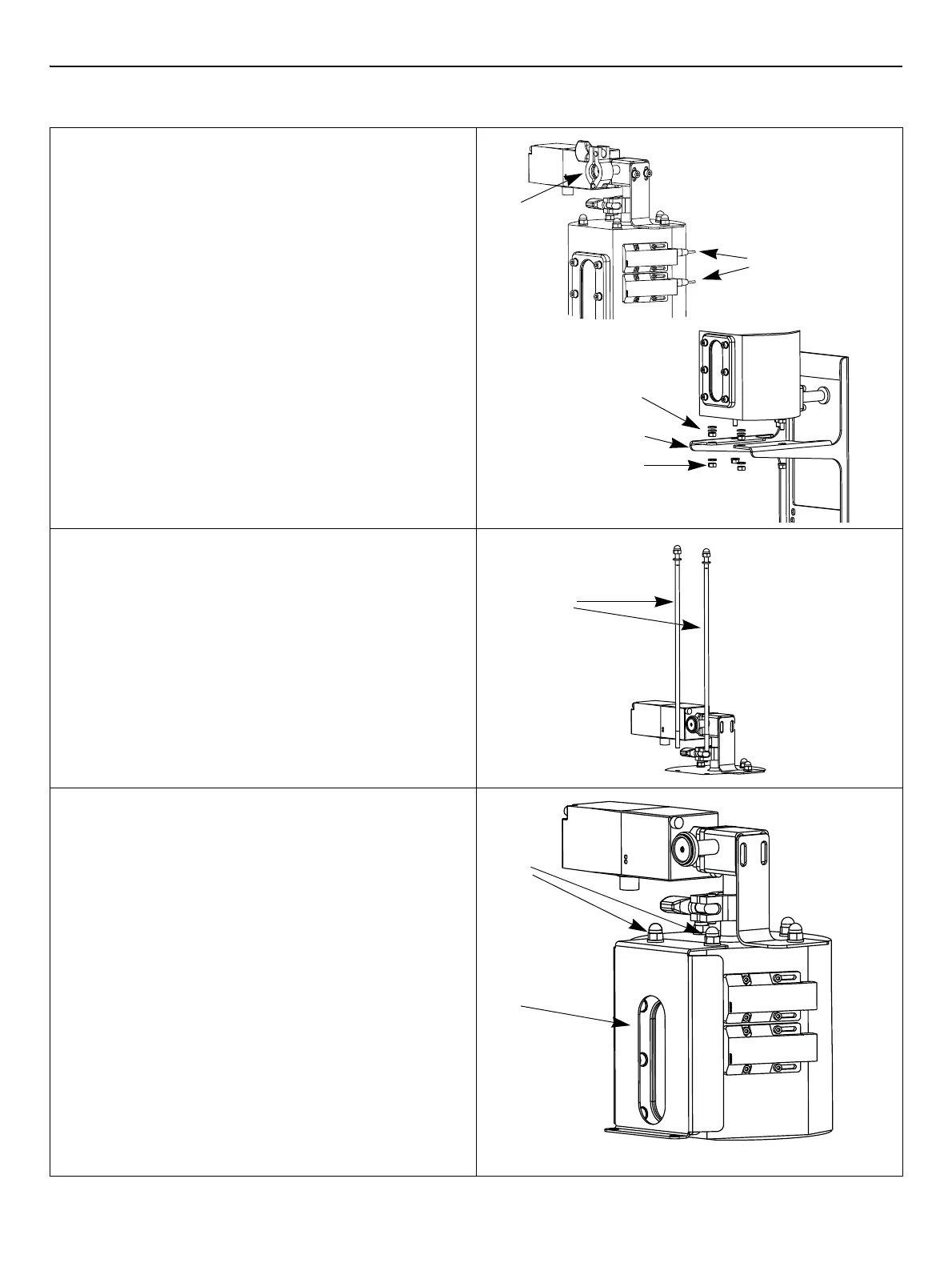
3 Mount the top sightglass cover part
• Place the top cover (G) on the air trap, with the opening
aligned with the sight glass.
• Re-insert the front two connecting rods (F) through the top
holes in the cover.
• Insert a plain washer and a lock washer on each of the
two front connecting rods underneath the air trap and
mount the nuts (C).
Note: The lock washer should be closest to the nut.
• Tighten the nuts using a torque of 3 Nm (±0.3 Nm). Verify
also that the other three nuts are tightened, using the
same torque value.
• Return the air trap to the support (D), aligning the bottom
part of each connecting rod through the holes in the
support.
• Connect the air trap inlet and outlet to the system valves.
 Loading...