28-9067-71 AA 07/2007
For contact information for your local office, please visit
www.gelifesciences.com/contact
GE Healthcare Bio-Sciences AB
Björkgatan 30
751 84 Uppsala
Sweden
www.gelifesciences.com/protein-purification-bioprocess
GE, imagination at work, and GE monogram are trademarks of General Electric Company.
Drop Design, ÄKTA and ÄKTAprocess are trademarks of GE Healthcare companies.
All third party trademarks are the property of their respective owners.
© 2007 General Electric Company—All rights reserved
First published Jul. 2007
All goods and services are sold subject to the terms and conditions of sale of thecompany within GE
Healthcare which supplies them. A copy of these terms and conditions is available on request. Contact
your local GE Healthcare representative for themost current information.
GE Healthcare Limited
Amersham Place, Little Chalfont, Buckinghamshire, HP7 9NA, UK
GE Healthcare Bio-Sciences Corp.
800 Centennial Avenue, P.O. Box 1327, Piscataway, NJ 08855-1327, USA
GE Healthcare Europe GmbH, Munzinger Strasse 5
D-79111 Freiburg, Germany
GE Healthcare Bio-Sciences KK
Sanken Bldg., 3-25-1, Hyakunincho, Shinjuku-ku, Tokyo, 169-0073 Japan
28-9266-70 AA Sightglass cover assembly instruction
Air trap parts number list
Air traps with the part numbers listed below must be fitted with the sightglass cover assembly:
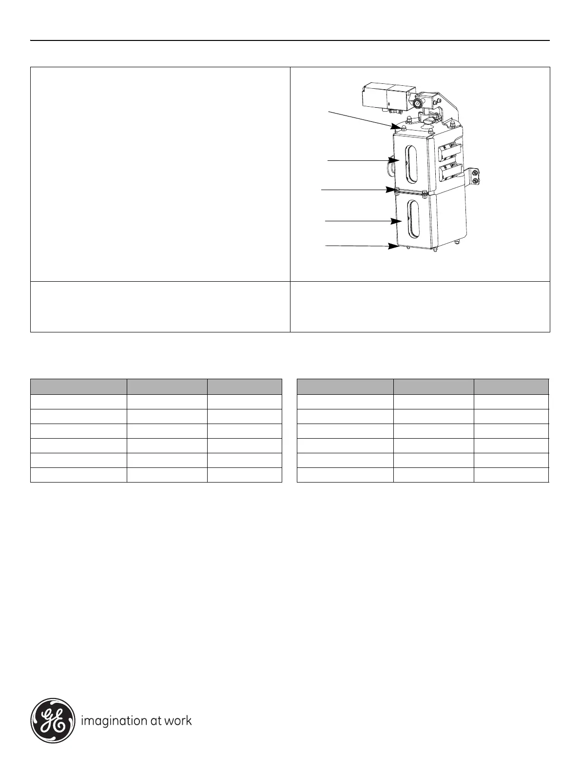
3 Mount the sightglass covers
• Place the top cover (D) on the air trap, with the opening
aligned with the sight glass.
• Re-insert the front two connecting rods (C) through the top
holes in the cover.
• Slide the bottom cover (E) over the lower ends of the two
front connecting rods (C) and align the corresponding
holes on both cover parts.
• Replace the bottom nuts (B) and washers on the front
connecting rods underneath the air trap.
• Tighten the nuts using a torque of 3 Nm (±0.3 Nm). Verify
also that the other three nuts are tightened, using the
same torque value.
• Fasten the two cover parts together using bolts, washers
and nuts (F) as described in the mount procedure for 6
mm/0.5 inch systems.
4 Final connections
• Reconnect the TC coupling and evacuation hose to the top
valve (A).
Dimension Material Part number
6 mm PEEK/EPDM 03-0111-41
6 mm PEEK/FEP 03-0111-42
1/2 inch PEEK/EPDM 03-0111-39
1/2 inch PEEK/FEP 03-0111-40
6 mm PP/EPDM 03-0111-45
6 mm PP/FEP 03-0111-46
Dimension Material Part number
1/2 inch PP/EPDM 03-0111-43
1/2 inch PP/FEP 03-0111-44
1 inch PEEK/EPDM 28-4051-68
1 inch PEEK/FEP 28-4051-70
1 inch PP/EPDM 28-4051-69
1 inch PP/FEP 28-4051-71
 Loading...