Troubleshooting
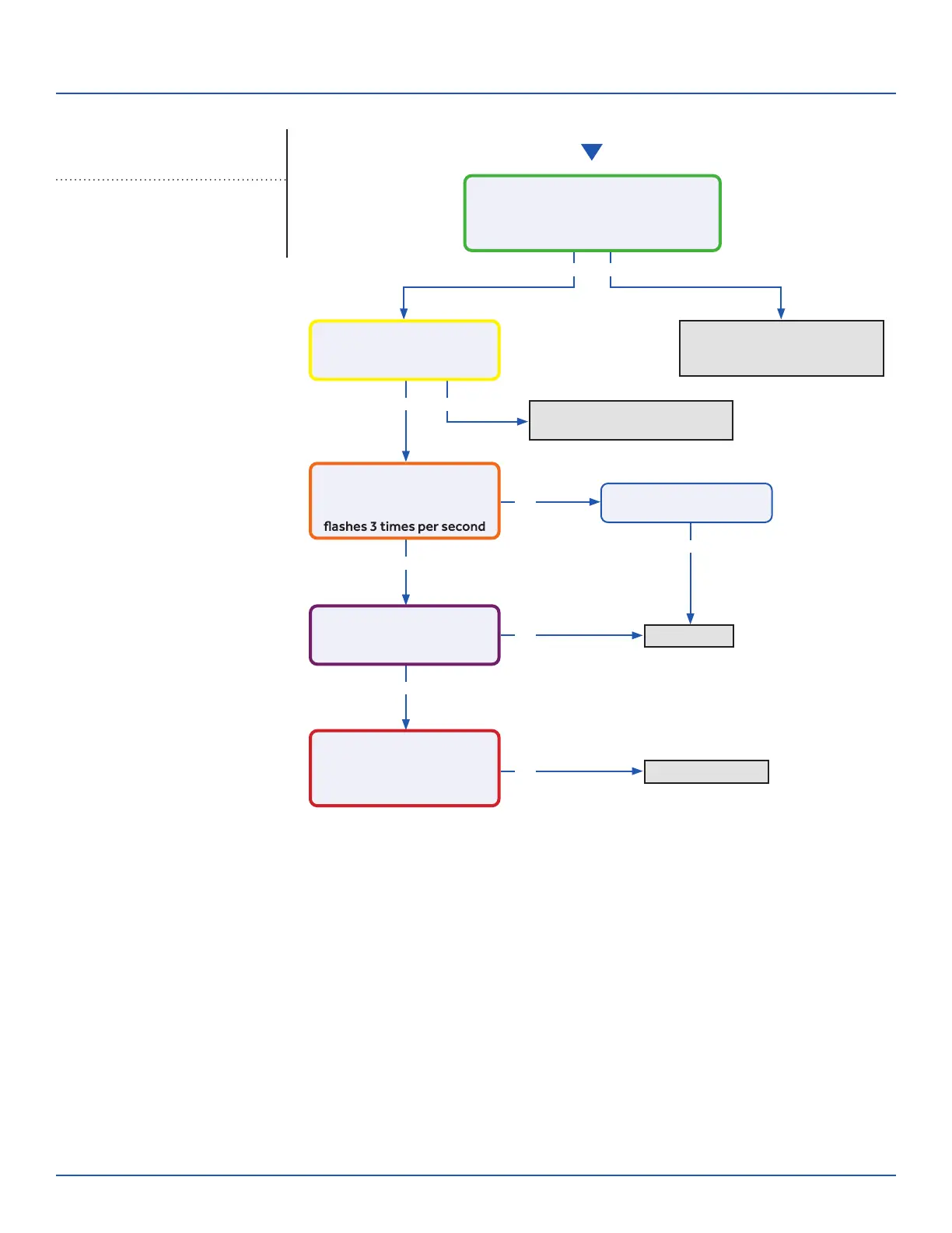
Start
See reverse side for
wiring diagram and
relevant color-coded
test positions.
Yes
Yes
Yes
Yes
No
No
No
Yes No
No
Determine source of lost
power from OD unit or phase
imbalance from building power
Determine source of lost
communication from OD unit
Replace PCB
Replace sensor
There is 230 VAC (+/- 10%) at terminal
strip connections 1(N) and 2(L), and
no more than a 2% deviation between
each leg and ground?
There is a pulsing 0 to 80
VAC between terminal strip
connections 1(N) and 3(C)?
There is 230 VAC at
terminals CN17 and CN21
on the PCB, and the LED
There is 5 VDC at CN6
across both sets of black
sensor wires?
The sensor resistance is
within 3% of the value listed
in the Service Manual sensor
resistance table?
Wiring and connections
are in good condition?
Check This First
Indoor Unit
Models:
ERROR CODES and Troubleshooting
PAGE 29
ASYW09CRAWA
ASYW12CRAWA
ASYW18CRDWA
ASYW24CRDWA
 Loading...