17 18
4.4 Communication Connection
Inverter operation data can be transferred by RS485, or WIFI Modular to a PC with monitoring
software or to data logger device such as Ezlogger Pro. RS485 is the standard communication
choice for inverter, and WIFI modular can be used optionally for communication.
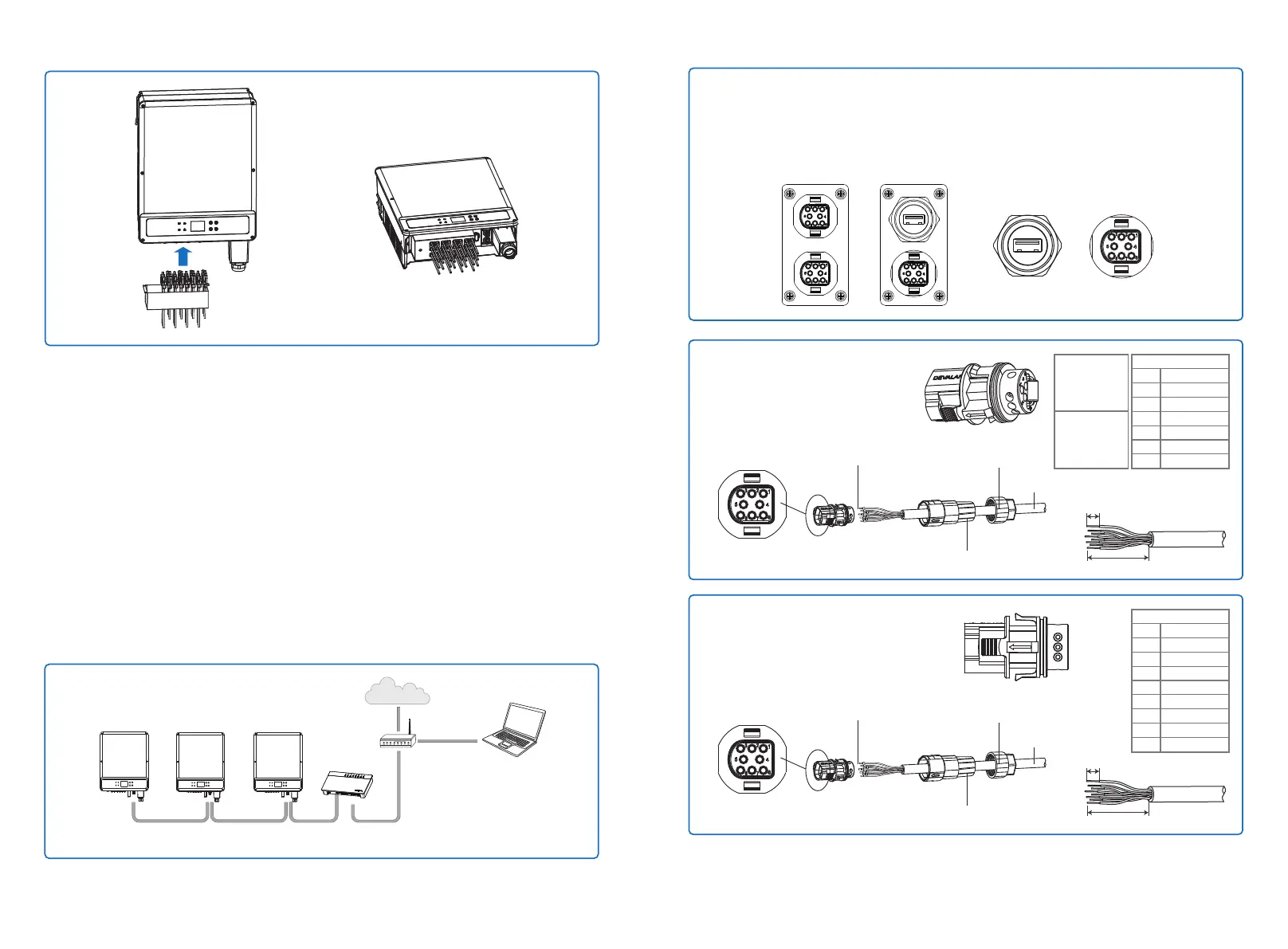
4.4.1 RS485 / DRED / Remote Shutdown Communication
The RS485 port of inverter is used to connect the EzLogger Pro, and the total length of connect-
ing cable should not exceed 1000m.
DRED(Demand response enabling device) is only for Australian ande New Zealand installations,
in compliance with Australian and New Zealand safety requirements. DRED is not provided by
manufacturer.DRM function is achieved by Ezlogger Pro or DRED COM port , and please connect
the Ezlogger Pro through RS485 port. Detailed DRED connection refer to Ezlogger Pro manual.
Communication cable must be separated from other power cable to prevent the communication
from being interfered. RS485 connection please refer to the figure below.
Inverter
RS485
EzLogger Pro
RS485RS485
PCRouter
Internet
Inverter
Inverter
Detailed operation steps of series are as follows:
Step 1:
Plug out the terminal and dismantle the resistor / short wire, if you want use the DRED and
Remote shutdown function.
Note: DRED should be connected through "COM port".
Step 2-1 For DRED:
Put the cable through the plate.
6.5mm
30mm
Tightening the screws and the
screws are not over the surface
Cables
The Insulator
Screw Cap
No.
1
2
3
4
5
6
Function
DRM1/5
DRM2/6
DRM3/7
DRM4/8
REFGen
Com/DRM0
DRED
RS 485
USB
RS 485
USB
8pin
DRED
Step 2-2 For RS485:
Put the cable through the plate.
6.5mm
30mm
Tightening the screws and the
screws are not over the surface
Cables
The Insulator
Screw Cap
No.
1
2
3
4
5
6
7
8
Function
485-A1
485-B1
485-A1
485-B1
485-A2
485-B2
GND
VCC
RS 485
Wiring diagram of Australia
1.Maintain
current
access to
normal boot.
2.Join up DRED
should take
down the 15k
resistance.