1
,QVWDOODWLRQ,QVWU X FWLRQV
*(,QWHUORJL[
'
PRELIMINARY 10/1/03
Product Summary
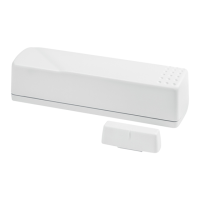
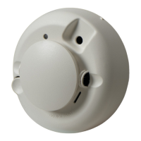
The Learn Mode Shock Sensor has the following three main
functions:
• To detect the vibrations made by an intruder trying to
break a window or door.
• To detect a window or door opening.
• To detect tamper situations, such as an intruder remov-
ing the sensor cover or the sensor from the wall.
Vibrations cause a momentary open circuit in the shock ele-
ment of the sensor. The circuit closes again when the vibra-
tion stops. The sensor microcontroller “sees” the open/close
action as a pulse, causing the sensor to transmit an alarm
signal. The sensor has two different detection modes:
• Gross Attack - detect a violent blow sufficient in length to
trip sensor.
• Pulse Count - detect a sufficient number of less violent
blows (rapping or tapping).
The sensor includes an internal magnetic reed switch that
must be disabled if it is not used.
Extend the battery life of the sensor by adding a second 3-
volt lithium battery.
Installation Guidelines
• Learn the sensor before adjusting the shock sensitivity.
The sensor is shipped with the reed switch enabled and
open, and this is how it must be learned.
• Before permanently mounting the sensor, test it at the
intended location to make sure that the panel can
receive sensor signal transmissions. The sensor is an
RF device and there may be blind or non-operational
locations within the installation. Normally, these can be
overcome by moving the sensor or receiver.
• Always mount the shock sensor so that the detector is on
the frame and not on the glass. See Figure 2 for mount-
ing locations.
• Mount the sensor in a location where the structure can
transmit vibrations to the sensor.
• The sensor can be mounted on a vertical surface or on a
horizontal (flat) surface.
• Make sure the window fits snugly in the frame and
doesn’t move or rattle.
• Hold the sensor against the frame to make sure the sen-
sor base fits on the surface area of the frame and doesn’t
extend over the surface edges.
Figure 1. Mounting Options for Door/Window Sensor
Tools and Supplies
•
Control panel installation instructions
• Phillips screwdriver
• Slotted screwdriver (to pry off the cover)
• Two #6 x 2 cm flathead screws for mounting the sensor
(included)
• Two #6 x 1.5 cm screws for mounting the magnet
(included)
Vertical (Wall) Surface Mounting
Horizontal (Ledge) Surface Mounting
Shock Sensor
Shock Sensor
Shock Sensor
Shock Sensor
/HDUQ0RGH6KRFN6HQVRU
Document No. 466-2023 Rev. A
September 2003