Masoneilan 496 Series Rotary Electric Switch Instructions Manual | 2© 2015 General Electric Company. All rights reserved.
1. Introduction
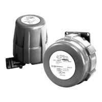
Series 496 rotary switches are used for electrically indicating
one or two predetermined positions in the stroke of a control
valve. They may be connected to audible alarms or signal
lights for warning of valve or system malfunction. These
switches may also be used to actuate solenoids, relays and
other electrical devices.
Basic switches (4) in the unit are single pole, double throw
snap acting and are individually adjusted by cams (13) on
the rotating shaft (11). Vernier adjustment is made by means
of locking type set screws (Nylock) (2) in the cams and these
screws actuate the switches by contacting the switch spring
levers. The spring levers provide overtravel protection and
allow maintained contact when required. The Series 496
is available with either one or two switches, each with an
adjustable cam to actuate it.
The housing and cover are made of anodized aluminum and
are explosion proof. In addition, O-ring seals
(7 and 10) in the cover and rotary shaft, make the
switch waterproof.
Series 496 switches may be mounted on the 35002
Series Camflex, 30000 Series Varimax, 36002 Series Control
Ball and 37002 Series MiniTork Butterfly valves. Also, the
addition of a standard back lever and linkage permits its use
with the 10000 and 21000 Series and linear motion valves.
For complete parts list for the Series 496 switch refer to Parts
Supplement FS7000.
2. Operation
The motion of the control valve turns by means of a back lever
(or coupling) the switch shaft (11). Cams (13), fastened to the
shaft by screws (1), actuate microswitches (4) by pushing levers
(5). Each switch may be wired to either open or close the circuit
when the lever is depressed.
3. Installation
Only two couplings are used to connect the switch shaft (11)
to the valve; a strip type coupling (Ref. 9, Figure 3) for rotating
shaft valves and a back lever (Ref. 9, Figure 6)
for linear motion valves. Each is fastened to the switch shaft
(11) with a spring washer and cap screw. Refer to Figures 3
through 7 for mounting details.
Microswitches are rated at 10, 15 or 20 amps at 115 or 230
volts dc. Check the rating printed on each switch. Each
microswitch has three terminals. The lower one is common,
the middle terminal is for normally open circuit; the top
terminal is for normally closed circuit. Pass wiring through the
3/4" NPT port in the bottom of the case.
4. Adjustments
The Series 496 switch is normally mounted and adjusted on
a control valve at the factory. To adjust the instrument in the
field, proceed as follows:
A. The concave part of the levers (5) should be exactly
concentric with the cams (13) with the switch actuated.
This is an important step to assure that once the lever is
depressed, it stays depressed during overtravel (if any).
If not, loosen screws (3 and 17) and slide the levers up or
down slightly. Tighten screws (3).
B. Unscrew slightly the cam locking screws (1) using a 3/32"
Allen wrench.
C. Actuate the valve to the desired position (usually the full
opened or full closed position).
D. It is important to note that the cam operating the right-
hand switch should make contact with lever (5) only at
the end of a counterclockwise rotation.
This assures that when the valve is throttling, the screw
(2) is completely free of the lever. The concave part of the
lever is only to maintain contact during
over-travel (if any). Similarly, the cam operating
the left-hand switch should make contact with
lever (5) only at the end of a clockwise rotation. If there
is only one switch (Model 496-1) it may be necessary to
reverse the position of the switch from left to right or vice
versa depending on the rotation and stroke position.
E. Turn the cam (13) on the shaft until the switch is a
voltmeter.) Lock the cam (13) with screw (1).
F. Make a fine adjustment with screw (2) using a
1/16" Allen wrench. The screw (2) must extend out from
the cam far enough to assure sufficient depression of
lever (5).
 Loading...