GE Profile Arctica
®
and GE CustomStyle
™
side-by-side installation information & specifications
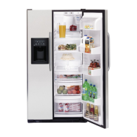
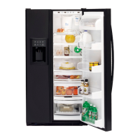
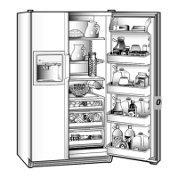
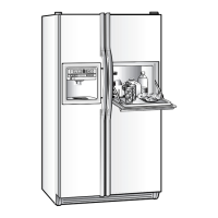
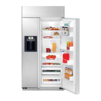
Create a custom look for your GE Profile CustomStyle side-by-side refrigerator
Still another advantage offered by GE Profile CustomStyle Refrigerators is ease of
installation. For a refrigerator that does so much to enhance the beauty of your kitchen,
the “behind-the-scenes” preparation and installation are surprisingly simple.
W3624
1/2" to 3/4" Side Panel
Side
Trim
Route
hand slot
before
installing
panel.
Select appropriate
si
ze door panel from
cabinet line.
W
A
T
E
R
C
R
U
S
H
E
D
C
U
B
E
D
R
E
S
E
T
W
A
T
E
R
F
I
L
T
E
R
H
O
L
D
3
S
E
C
S
Q
U
I
C
K
I
C
E
L
I
G
H
T
D
O
O
R
A
L
A
R
M
L
O
C
K
C
O
N
T
R
O
L
H
O
L
D
3
S
E
C
S
Fabricating the enclosure
• The drawing shows an 84" cabinet elevation. Adjust dimensions accordingly for other
cabinet elevations.
• Cabinet pieces to order: (2) side panels and (1) wall cabinet.
• Side panels will typically be attached to adjacent cabinets and/or cleated to rear wall
and floor.
• Refer to GE refrigerator installation instructions for proper plumbing, and electrical and
air clearances.
• (1) Some framed cabinet lines will make a refrigerator enclosure with a cabinet 12" high
x 39" wide with sides and 1-1/2" face frame extended down to floor to create the
refrigerator space. This will replace the above construction. (2) A tall cabinet on either
side of the refrigerator can replace a side panel.
• Counter overhangs on either side of the refrigerator should have clipped corners to allow
for full door swing.
• If the refrigerator has a wall returning beyond the front of the refrigerator on either side,
a 2" tall filler will help allow for movement of the door.
Door Panels
• See drawings for exact dimensions of the fresh-food and freezer door panels.
• Refrigerator door fronts from stock and most semi-custom cabinet manufacturers will
be supplied as 1/4"-thick panels cut to dimensions, with closest available
standard door sizes applied to front.
– This will leave a “reveal” at top/bottom and sides. Width of “reveal” will depend
on manufacturer’s standard door sizes.
– Door will be affixed on the 1/4" panels at factory or in the field by the local
supplier, depending on manufacturer.
• Local shop-built or custom cabinet supplier may fabricate custom 3/4" panels.
In this case, edges must be routed.
• Follow notes on drawing to assure room for fingers/hands to open handles.
Standard, new construction
and replacement installation
Rough-in dimensions
• All wall/floor molding should be
removed prior to installation.
• Water recess on rear wall
recommended to prevent water line
damage. 48" minimum length,
1/4"-diameter water line tubing
recommended.
• When possible, recess both copper
water line and electrical outlet
(see local codes).
• Front and rear leveling legs are
adjustable for the built-in look
(see owner’s manual).
• If optional collar trim kit is to be used
or anticipated, see collar trim
installation on next page for
different rough-in dimensions.
Installation tips to
maximize the built-in look
8' Ceiling
13" to 14"
Cabinet
12"
Soffit
36-1/8"
24-1/2"
*The rough-in dimensions of 70-1/4"/72-1/4" are minimum and measured from
the finished floor to top of opening (or the underside of the overhead cabinets).
For Models with Trim Kit: If frameless style cabinets are planned for above the
refrigerator, you may need to consider adding a maximum of 1/4" (70-1/2") to
height of opening for 23 cu. ft. models and 1/8" (72-3/8") for 25 cu. ft. models
to allow additional clearance between cabinet doors and top of refrigerator trim
when cabinet doors are in open position.
Collar Trim In. w/ceiling
70-1/4"*
23 cu. ft. models
72-1/4"*
25 cu. ft. models
25"
Counter
Top
ElectricalWater
3/4" Airspace
(1/2" Gap + 1/4"
Wall Plates)
24"
Cabinet
25"
Counter
Top
Electrical Water
3/4" Airspace
(1/2" Gap + 1/4"
Wall Plates)
24"
Cabinet
25"
Counter
Top
Electrica
lWater
Trim
3/4" Airspac
e
(1/2" Gap + 1/4"
Wall Plates
)
24"
Cabinet
25"
Counter
Top
Electrical Water
Trim
3/4" Airspace
(1/2" Gap + 1/4"
Wall Plates
)
24"
Cabinet
FOR 21 CUBIC FOOT MODELS
FOR 24 CUBIC FOOT MODEL
S
Fig 2A eps
IMPORTANT: Before finalizing specifications
for your GE Profile CustomStyle Refrigerator,
please NOTE:
• A minimum width of 36" is required for
refrigerator installation
• Be sure to allow for 1/2" or 3/4" side panels
in addition to the 36" minimum
Installation of water outlets
Alternate
water
line location
through floor
1/2"
Water hook-up
on the refrigerator
Recommended water line
location using recess
in rear wall
Recommended
single loop of 1/4" copper water line
Water hook-up
on the refrigerator
Rear Wall View
18"
24"
Allow 48" minimum water
line to enable refrigerator
to be pulled forward
Alternate
water
line location
through floor
1/2"
Recommended water line
location using recess
in rear wall
Recommended single loop
of 1/4" copper water line
Water hook-up
on the refrigerator
Rear Wall View
Top View
Top View
18"
24"
Allow 48" minimum water
line to enable refrigerator
to be pulled forward
In.of water & Electric Ot. Art
Alternate
water
line location
through floor
1/2"
Water hook-up
on the refrigerator
Recommended water line
location using recess
in rear wall
Recommended
single loop of 1/4" copper water line
Water hook-up
on the refrigerator
Rear Wall View
18"
24"
Allow 48" minimum water
line to enable refrigerator
to be pulled forward
Alternate
water
line location
through floor
1/2"
Recommended water line
location using recess
in rear wall
Recommended single loop
of 1/4" copper water line
Water hook-up
on the refrigerator
Rear Wall View
Top View
Top View
18"
24"
Allow 48" minimum water
line to enable refrigerator
to be pulled forward
In.of water & Electric Ot. Art