– 29 –
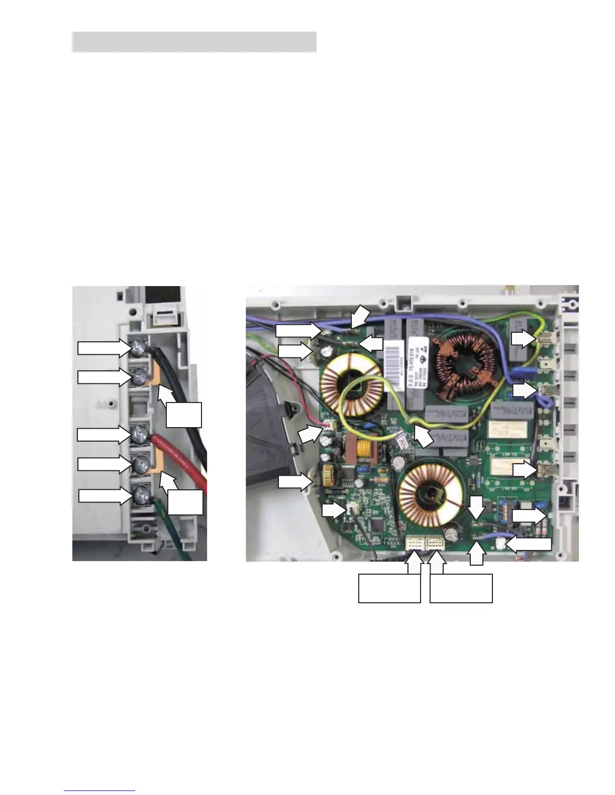
Filter Board
To remove the main fi lter board:
Remove the heat shield. (See 1.
Heat Shield.)
Lift the front of the module and mark the 2.
location of the black, red, and green wires and
the 2 jumper blades connected to the fi lter
board power terminals.
Using a T-20 Torx or a fl at blade screwdriver, 3.
remove the 4 screws, black and red wires, and
the 2 jumper blades.
Loosen the ground wire screw and remove 4.
the ground wire from the fi lter board power
terminal. Lower the module into the burner box.
5. Mark the location, then disconnect the black L1,
blue L2, and ground wire connections on the
fi lter board.
6. Disconnect the thermal cut-out, touch board,
and fan motor wire harnesses.
7. On 36-in. models, disconnect the fi lter-to-fi lter
wire harness.
8. Disconnect the LINbus connectors. (See
LINbus
Connectors.)
9. Using a fl at blade screwdriver, carefully press in
the large 1 (30-in. model) or 2 (36-in model) tabs
away from the fi lter board. Lift the fi lter board
and pull the fi lter board away from the smaller
tab on the module base.
Bottom of module shown
Tab
Tab
Tab
LINbus
LINbus
Arrows indicate disconnect locations
Remove
Remove
Remove
Remove
Loosen
Jumper
Blade
Jumper
Blade
Touch Board
Wire Harness
Filter-to-Filter
Wire Harness
Note
To remove the left side fi lter board on the 36-in. model, follow steps 1, and 5 through 9. The touch board •
wire harness is not connected to the left side fi lter board.
The left side fi lter utilizes a non-replaceable fuse. Never attempt to replace the fuse. If the fuse is found to •
be open, replace both left side fi lter and generator boards.
 Loading...