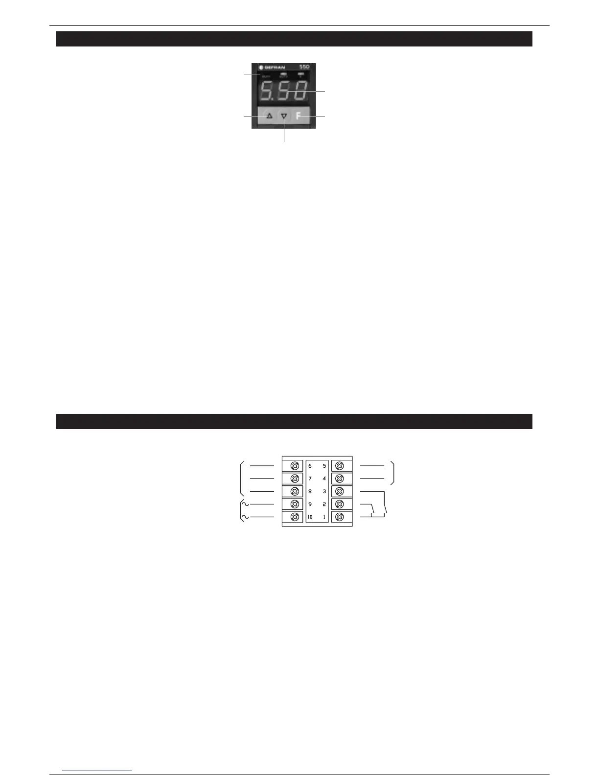
3 • FACEPLATE DESCRIPTION
4 • CONNECTIONS
INPUTS
INPUT 1
Digital input from mechanical contact or AC voltage (see order code)
between terminals 1 and 2 with the following function:
- Timer Start/Stop or Start/Reset
- Counter input pulses. Voltage level for AC input is the same as required
power supply.
INPUT 2 (use only if INPUT is from mechanical contact)
Digital input from mechanical contact between terminals 1 and 3 with the
following function:
- Timer reset
- Counter Start/Reset
- Frequency pulses from solid state sensor for revolution check
- Delay
Note: If both inputs are used, with one of two in AC voltage (24, 110 or
220Vac), you have to use an external AC/DC adapter (see connection dia-
gram).
OUTPUTS:
Two relay outputs (5A/220Vac)
OUTPUT1
Available to terminals 8 (NO contact), 7 (common) and 6 (NC contact).
OUTPUT2
Available to terminals 5 and 4 (NO or NC contact) selectable with jumper to
solder.
POWER SUPPLY
AC Voltage is applied to terminals 9 and 10 (110/220V selected with
jumpers to solder).
Voltages available on request: 24Vdc/110/220/120/240/24/48Vac;
Vac 50/60Hz ± 10%; 24Vdc, -10%+20%
With 24 Vdc, polarity is not critical. See Hardware Configuration.
A Display
Real value of current time/count (countdown).
In configuration phase, description of functions and/or parameters flash-
es alternately with value. Flashing of decimal point on right display indi-
cates:
- the display/setting of time 2/count 2 is selected;
- time 2/count 2 is active.
“EEP” alarm message
This message indicates an EEPROM memory fault; if it persists, send
the instrument back to the factory for repair.
E LED signals
The LEDs show the state of the two output relays (LED on = relay ener-
gized) - OUT1, OUT2.
The LEDs show the state of the Input 1 signal (timer input or input puls-
es to counter):
- LED K off (control inactive) corresponds to input open;
- LED K on (control active) corresponds to input closed.
With jumper S5 open and S6 closed, this state can be reversed (see
configuration).
CONTROLS
B FUNCTION Button
Used to access display/setting phase for Time 2/Count 2 setpoint
(decimal point flashes on right display) and confirms modification of
setpoints.
If the F button is not pushed to confirm a change, the new value will
be stored automatically after 5 seconds.
Push the F button for 5 seconds to access the configuration phase.
Scroll the
functions to be set by means of short pulses.
To quit configuration, push the F button again for 5 seconds.
NOTE: It is not necessary to press the F key to display/modify Time
1/Count 1.
D/C Raise/Lower Buttons
These are used to raise or lower the value displayed in order to
change a setting or choose an option.
The speed of raising (lowering) is proportional to the time for which
the key is pressed. The operation is not cyclical.
When the maximum (minimum) value is reached, the raise (lower)
function causes an automatic scale change (or if configured other
than standard, the function remains blocked in the selected scale).
In normal operation, Time 1/Count 1 (setpoint) can be changed
directly. If no button is pushed for about 5 sec, the display returns
to the current active time.
During the Configuration Phase, the raise (lower) button stops the
alternating description/value display. The display shows the value
to be displayed/modified for about 5 seconds.
A
E
D
BC
 Loading...