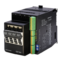
Cencal Out 4Modbus
• Serial line / output 4
Advice for Correct Installation for EMC
Instrument power supply
• The power supply to the electronic equipment on the
switchboards must always come directly from an isolation
devicewithafusefortheinstrumentpart.
• The electronic instruments and electromechanical power
devicessuchasrelays,contactors,solenoidvalves,etc.,must
alwaysbepoweredbyseparatelines.
• When the electronic instrument power supply is strongly
disturbed by the commutation of transistor or power units
or motors, an isolation transformer should be used for the
controllersonly,earthingthescreen.
• Itisessentialthattheplanthasagoodearthconnection:
-thevoltagebetweenneutralandearthmustnotbe>1V
-theOhmicresistancemustbe<6W;
• Ifthemainsvoltagefluctuatesstrongly,useavoltagestabilizer.
• In the proximity of high frequency generators or arc welders,
useadequatemainsfilters.
• The power supply lines must be separate from the instrument
inputandoutputones.
Inputs and outputs connection
• Theexternallyconnectedcircuitsmustbedoublyisolated.
• To connect the analogue inputs (TC, RTD) the following is
necessary:
-physicallyseparatetheinputcablesfromthoseofthepower
supply,theoutputsandthepowerconnections.
-usewovenandscreenedcables,withthescreenearthedin
onepointonly
• To connect the regulating and alarm outputs (contactors,
solenoid valves, motors, fans, etc.), fit RC groups (resistance
andcondensersinseries)inparalleltotheinductiveloadsthat
operateinAlternatingCurrent.
(Note: all the condensers must conform to VDE (class X2)
standards and withstand a voltage of at least 220V AC. The
resistancesmustbeatleast2W).
• Fit a 1N4007 diode in parallel with the coil of this can be
removedinductiveloadsthatoperateinDirectCurrent.
GEFRAN S.p.A. declines all responsibility for any
damage to persons or property caused by tampering,
neglect, improper use or any use which does not
conform to the characteristics of the controller and to
the indica tions given in these Instructions for Use.
Warnings and instructions for mounting to the panel
Instructions for installation category II, pollution
level 2, double isolation.
• only forlow powersupply: supply fromClass 2or lowvoltage
limitedenergysource.
• the power supply lines must be separate from the controller
inputandoutputones
• grouptheinstrumentstogetherkeepingthemseparatefromthe
poweredpartoftherelay
• do not install high-power remote switches, contactors, relays,
thyristor power units (especially the “phase angle” type),
motors,etc.inthesameswitchboard
• avoiddust,humidity,corrosivegassesandheatsources
• do not block the ventilation holes: the working temperature
mustbebetween0...50°C
• surroundingair:50°C
• use60/75°Ccopper(Cu)conductoronly,wiresizerange2xNo
22-14AWG,Solid/Stranded
• useterminaltighteningtorque0.5Nm
Nominal ambient conditions
Before supplying the Controller with power, make
sure that the mains voltage is the same as that
shown in the last number of the order code.
600
ouT1
ouT2 ouT3
SV
ouT4
L1
L2
L3
F
8888
8888
This section contains the instructions necessary for correct
installation of the 600 controllers into the machine control
panel or the host system and for correct connection of the
controller power supply, inputs, outputs and interfaces.
Before proceeding with installation read the following
warnings carefully!
Remember that lack of observation of these warnings
could lead to problems of electrical safety and
electromagnetic compatibility, as well as invalidating
the warranty.
Electrical power supply
• the controller is NOT equipped with an On/Off switch: the user
mustprovideatwo-phasedisconnecting switch thatconformsto
the required safety standard (CE marking), to cut off the power
supplyupstreamofthecontroller.
Theswitch must be located in the immediate vicinity of the
controller and must be within easy reach of the operator. One
switchmaycontrolmorethanonecontroller.
• ifthecontrollerisconnectedtoNOTisolatedelectricalequipment
(e.g.thermocouples),theearthconnectionmustbemadewitha
specific conductor to prevent the connection itself from coming
directlythroughthemachinestructure.
600
CONTROLLER
INSTALLATION AND OPERATION MANUAL
Side1 1Dimensionsandcut-out;panelmounting
2Installationandconnection
3Descriptionoffaceplate
4Connections
Side2 5Technicalspecifications
6“Easy”programmingandconfiguration
7Quickstartguide
The complete manual is available for download from the
website www.gefran.com
GEFRANspareservestherighttomakeanyaestheticor
functionalchangeatanytimeandwithoutnotice.
cod.80311 - 11/2012 - ENG
1 • DIMENSIONS AND CUT-OUT;
PANEL MOUNTING
99
10
45
45
48
70
70
63
48
Forcorrectandsafeinstallation,
followtheinstructionsand
observethewarningscontained
inthismanual.
Panel mounting:
Tofixtheunit,insertthebracketsprovidedintotheseatsoneither
sideofthecase.
Tomounttwoormoreunitssidebyside,respectthecut-out
dimensionsshowninthedrawing.
2 • INSTALLATION AND CONNECTION
3 • DESCRIPTION OF FACEPLATE
Automatic/ManualadjustmentselectionActiveonlywhenPV
displayvisualisestheprocessvariable
Function indicators
Indicatesmodesofoperation
MAN/AUTO= OFF(automaticcontrol)
ON(manualcontrol)
SETPONT1/2= OFF(IN1=OFF-localSetpoint1)
ON(IN1=ON-localSetpoint2)
SELFTUNING=ON(enabledSelf)
OFF(disabledSelf)
“Inc” and “Dec” key
Presstoincrement(decrement)anynumericalparameter••Increment(decrement)speedisproportionaltotimekeystays
pressed••Theoperationisnotcyclic:oncethemaximum(minimum)valueofafieldisreached,thevaluewillnotchangeevenif
thekeyremainspressed.
PV Display:Indicationofprocessvariable
ErrorIndication:LO,HI,Sbr,Err
LO=thevalueofprocessvariableis<diLO_S
HI=thevalueofprocessvariableis>diHI_S
Sbr=faultysensororinputvalueshigherthanmax.limits
Err=PT100thirdwireopenedforPT100,PTCorinput
valueslowerthanmin.limits(i.e.:TCwrongconnection)
Function key
Givesaccesstothevariousconfigurationphases••
Confirmschangeofsetparametersandbrowsesnextor
previousparameter(ifAuto/Mankeyispressed)
SV display:Indicationofsetpoint
Indication of output states
OUT1(AL1);OUT2(Main);OUT3(HB);OUT4(HB)
5Aat
250Vac/30Vdc
relay
Standard:
100...240Vac±10%
Optional:
11...27Vac/dc±10%
Max.power10VA;50/60Hz
4 • CONNECTIONS
• Ammeter outputs/input
6
5
4
3
2
1
7
8
9
10
11
12
18
17
16
15
14
13
19
20
21
22
23
24
19
21
20
22
-
+
Out2
Out1
• Power Supply
23
24
~
~
TOP
6
5
-
+
Out3(Al2)
Ing.T.A.
PWR
Standard
configuration
4...20mA
Connectat20mAinput
Usewiresof
adequatediameter
(min.1mm
2
)
PT100,JPT100,
PTC,NTC
• Pt100 / PTC / NTC
• Device structure • Identification of boards
3
1
2
Pt1003wires
PTC/NTC
/Pt1002wires
Availablethermocouples:
J,K,R,S,T
(B,E,N,L,U,G,D,Ccustomlinearization
isavailable)
-Observepolarities
-Forextensions,usethecorrect
compensatingcableforthetypeofTCused
+
-
• TC Input
2
1
4
2
3
1
+ 24Vo15V
VT
-
+
+
S
-
Ri=50Ω
4
2
3
1
+24Vo15V
VT
-
+
+
-
Ri=50Ω
T
T
• Linear input with 3-wire transmitter
• Inputs
• Input 1 linear with transmitter 2 wires
9
10
11
+
-
TX
A
(Data+)
RX
-
+
12
9
10
11
12
DISPLAY
POWER
SERIALINTERFACE/OUT4
Selectsignalat
contact3
CPUboard-Componentside
CPU
PT100
+VT
Linearinput
indccurrent
20mA,
Ri=50Ω
Linearinputin
dcvoltage
60mV,1VRi>1MΩ
5V,10VRi>10KΩ
2
1
+
-
• Linear input (I)
4
1
2
-
+
• Linear input (V)
RS485isolatedserialline
SeeserialcarddatasheetforCencalconfiguration
-5Aat250Vac/30Vdcrelay
-24V,10Vat20mAlogic
-triac20...240Vac,1A±10%
-Digitalinsulated24Vac/dc
-5A/250Vacrelayonly
-5Aat250Vac/30vdcrelay
-24V,10Vat20mAlogic
-continuous0…10V,0/4…20mA
-analog0…10V,0/4…20mAfor
transmission,resolution12bit
-inputfromcurrenttransformer
50mAac,10Ω50/60Hz
-logicinput24V,5mAorfrom
no-voltagecontact
-Digitalinsulated24Vac/dc
Userconfigurablegenericoutput
11
B
(Data-)
24V
15V
10V
5V
1,23V
R20
S2
NB.:youcankeeptheOUT1relayenergizedatpower-upby
insertingjumperS2andremovingresistanceR20.
IN/OUTboards
(seeappendix)
Powerboard-Solderside
Selecttransmitter
voltage
Altitude Upto2000m
Working/storage
temperature
0..50°C/-20...70°C
Noncondensing
relativehumidity
20...85%
GEFRAN spaviaSebina,74-25050Provagliod’Iseo(BS)
Tel.03098881-fax0309839063Internet:http://www.gefran.com
PV
• if the controller is used in applications with risk of damage to
persons,machineryormaterials,itisessentialtoconnectitup
toauxiliary alarmequipment. It isadvisable tomake surethat
alarmsignalsarealsotriggeredduringnormaloperation.
ThecontrollermustNOTbeinstalledinflammableorexplosive
environments; it may be connected to equipment operating
in such atmospheres only by means of appropriate and
adequatetypesofinterface,conformingtotheapplicablesafety
standards.
Notes Concerning Electrical Safety and
Electromagnetic Compatibility:
CE MARKING:
The instrument conforms to the European Directives 2004/108/
CEand2006/95/CEwithreferencetothegenericstandards:
EN 61000-6-2(immunityinindustrialenvironment)EN 61000-6-3
(emissioninresidentialenvironment)EN 61010-1(safety).
Series 600 temperature controllers are mainly designed to
operateinindustrial environments, installedontheswitchboards
orcontrolpanelsofproductiveprocessmachinesorplants.


 Loading...