ADL500 • Quick installation guide - Specifications and connection 31
7.3.3 Feedback Connection
Note!
For terminal location see section "7.1 Location and identification of terminals and LEDs" on page 26.
XER terminal
Pin Signal Description Direction ADL510 ADL530 ADL550
20 BR– Channel B (–) repeat OUT Yes Yes Yes
21 BR+ Channel B (+) repeat OUT Yes Yes Yes
22 AR– Channel A (–) repeat OUT Yes Yes Yes
23 AR+ Channel A (+) repeat OUT Yes Yes Yes
XE terminal
Pin Signal Description
Digital
Incremental
Sinusoidal
Incremental
Sinusoidal
Incremental +
Sin/Cos
Sinusoidal
Incremental +
Absolute
Direction ADL510 ADL530 ADL550
#1 #2
1 FH2 Fast (Freeze) 2 input x x x x IN - - Yes
2 FH1 Fast (Freeze) 1 input x x x x IN - - Yes
3 COM_FH Common Fast inputs x x x x IN - - Yes
4 COS– DT– Channel Cos - / Data - x x IN / BID - Yes Yes
5 COS+ DT+ Channel Cos + / Data + x x IN / BID - Yes Yes
6 SIN– CK– Channel Sen - / Clock - x x IN / OUT - Yes Yes
7 SIN+ CK+ Channel Sen + / Clock + x x IN / OUT - Yes Yes
8 Z– Channel Z – x x x x IN Yes Yes Yes
9 Z+ Channel Z + x x x x IN Yes Yes Yes
10 B– Channel B – x x x x IN Yes Yes Yes
11 B+ Channel B + x x x x IN Yes Yes Yes
12 A– Channel A – x x x x IN Yes Yes Yes
13 A+ Channel A + x x x x IN Yes Yes Yes
14 0VE Encoder reference x x x x OUT Yes Yes Yes
15 +VE Encoder supply x x x x OUT Yes Yes Yes
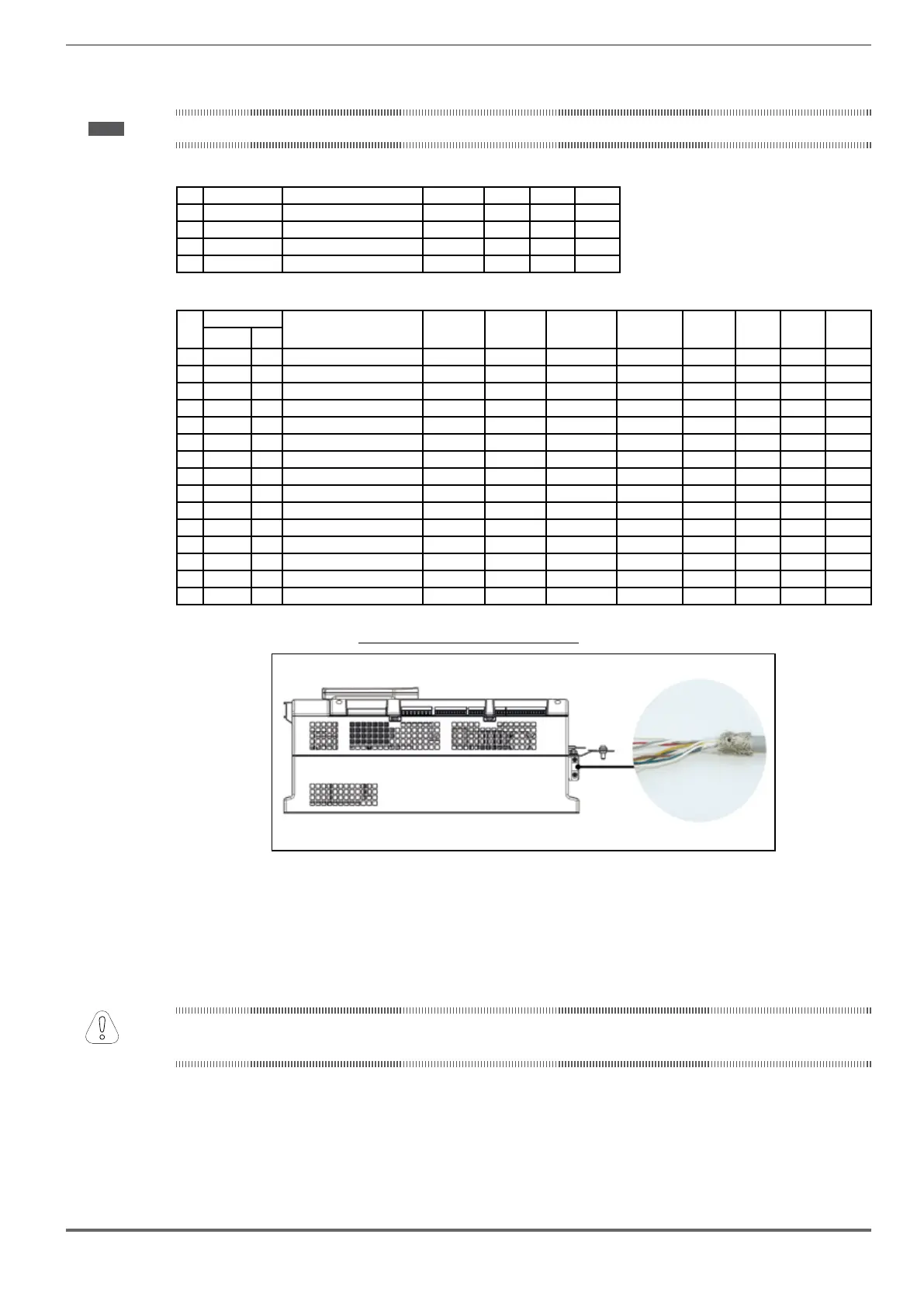
Figure 7.3.2: Connection of shielding (recommended)
Encoders provide motor speed and position feedback.
The regulation algorithms in the ADL500 drive are capable of controlling asynchronous and permanent magnet
synchronous (brushless) motors. With asynchronous motors the regulation algorithm may or may not use the speed
measurement obtained from the encoder reading. With brushless motors the regulation algorithm needs an encoder
ADL500 supporta diversi tipi di encoder.
The type of encoder that is connected must be selected via software: PAR 2132 Encoder mode (menu ENCODER).
next table:
 Loading...


