653, 654
12 / 28
11.3 Setting the seal adjuster
and the stroke limiter
Important:
Only set the seal adjuster and
stroke limiter when the valve
is completely assembled (with
diaphragm and valve body) and in
a cold condition!
GEMÜ 654 bonnet size 0TH
Diaphragm size 8
15
4
Greased
thread
9
3
10
Greased
O-rings
5
12
7
6
13
11
8
Setting the seal adjuster
G Unscrew locking screw 8 and remove it.
G Pull off handwheel 7.
G Loosen locking screw 9 with a SW2 Allen
key (do not unscrew it completely).
G Unscrew stroke limiting sleeve 5 and
remove it.
G Loosen lock nut 6 with a SW19 open-end
wrench and unscrew it by 2 to 3 turns.
G To deactivate the seal adjuster loosen the
seal adjuster nut 13 with a SW19 open-
end wrench unscrew it by 2 to 3 turns.
G Place handwheel 7 upside down on the
double flats of the threaded spindle 15.
Gently close the valve with handwheel 7
("CLOSED position") (valve is tight).
G Screw in the seal adjuster nut 13 until it
stops and secure with lock nut 6 (SW19
open-end wrench).
Setting the stroke limiter
G Move the valve to the OPEN position by
turning handwheel 7 (upside down) until
the required flow rate is reached.
G Pull of handwheel 7 from the threaded
spindle 15.
G Screw stroke limiting sleeve 5 on until it
stops.
Important:
The threaded spindle 15 must
not turn during this process!
If necessary, hold with a SW8
open-end wrench!
G Fix the stroke limiting sleeve 5 with
locking screw 9 (SW2 Allen key).
G Push handwheel 7 into its original
position on the double flats of the
threaded spindle 15 and secure it with
locking screw 8.
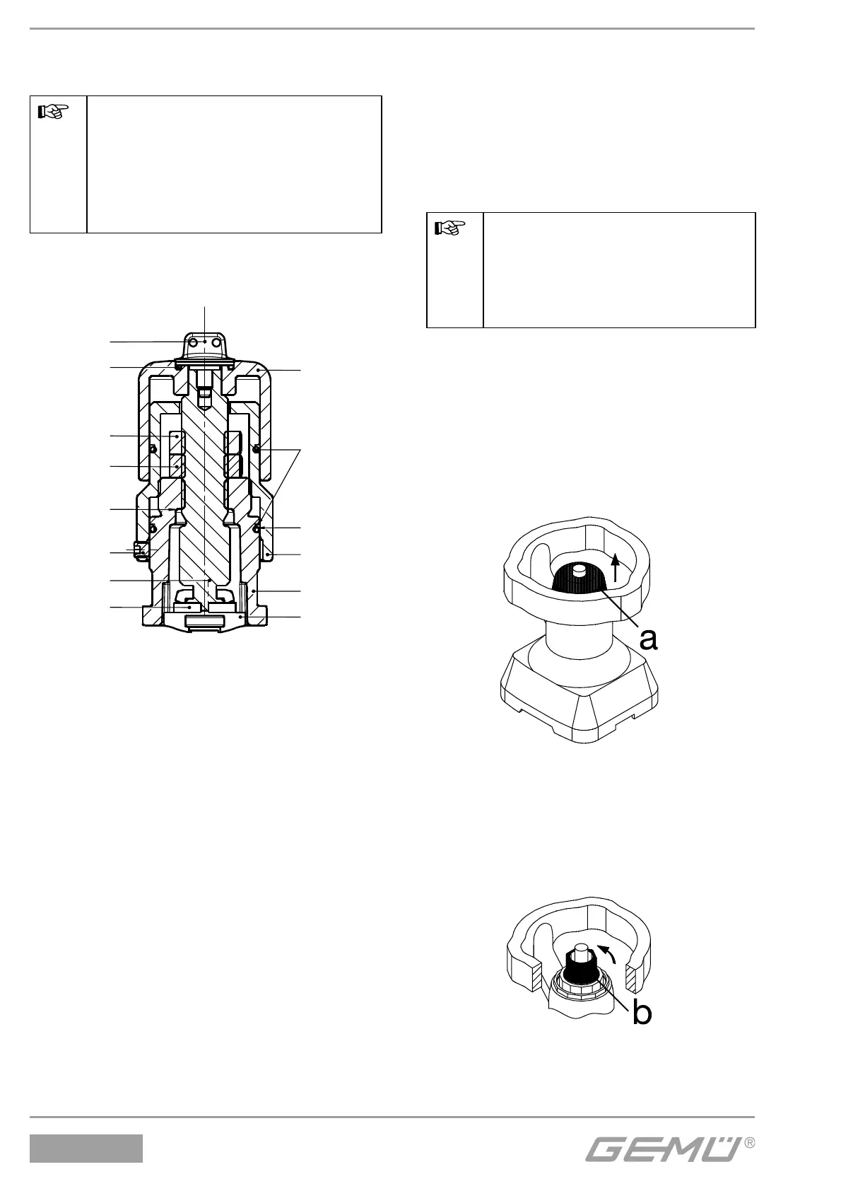
Diaphragm sizes 10 - 50
Preparation for setting
G Remove protective cap a.
G Move the bonnet out of the end positions
to enable the handwheel to be turned in
both directions.
Releasing the stroke limiter
G Turn stroke limiter b anticlockwise
upwards until the male thread is visible.

 Loading...