Page 4
Connections
1. Make sure that the POWER (6) switch is in the OFF position. This unit
comes supplied with a 15 volt AC adaptor. Plug the male pin of the
adaptor into the rear panel POWER JACK (7). Then plug the adaptor
into a proper power source.
2. The MASTER OUTPUT (1) jacks are unbalanced and used to connect
to your main amplifier.
3. The DJ MIC (18) input (found on the front panel) accepts a 1/4"
connector and balanced and unbalanced microphones.
4. On the rear panel are 2 stereo PHONO/LINE (3, 4) inputs, 1 stereo
PHONO (5) input and 1 stereo LINE (2) input. The PHONO/LINE
SWITCHES (8, 10) enable you to set the (3, 4) inputs to Phono or Line.
The phono inputs will accept only turntables with a magnetic cartridge.
A GROUND SCREW (9) for you to ground your turntables is located on
the rear panel. The stereo line inputs will accept any line level input
such as a CD player, a cassette player, etc.
5. Headphones can be plugged into the front panel mounted PHONES
(36) jack.
Operation
1. POWER ON: Once you have made all the equipment connections to
your mixer, press the POWER (6) switch. The power will turn on and
the POWER LED (23) will glow RED.
2. CHANNEL 1: The GAIN (11), HIGH (12), MID (13), and LOW (14)
controls allow you to fully adjust the selected source. Switch # (15)
allows you to select either the PHONO 1 (5) or the PHONO 2/LINE 1
(4) input. The CHANNEL SLIDE (16) controls the output level of this
channel.
3. CHANNEL 2: The GAIN (29), HIGH (30), MID (31), and LOW (32)
controls allow you to fully adjust the selected source. Switch # (33)
allows you to select either the PHONO 3/LINE 2 (3) or the LINE 3 (2)
input. The CHANNEL SLIDE (34) controls the output level of this
channel.
4. KILLING LOW FREQUENCIES: You can use the Kill Feature on each
channel to remove Low band frequencies to create special effects
and improve your mix. Move the KILL SWITCH (17) down to remove
the low band of Channel 1 from your mix. Move the KILL SWITCH
(35) down to remove the low band of Channel 2 from your mix.
5. CROSSFADER SECTION: The CROSSFADER (27) allows the mixing of
one source into another. The left side of the CROSSFADER (27) is
CHANNEL 1 and the right side is CHANNEL 2. The CROSSFADER (27)
in your unit is removable and if the need arises can be easily replaced.
Crossfader units are available in three varieties. Part # RF-45 (which
is identical to the crossfader supplied with the mixer) has a 45 mm
travel from side to side. Part # RF-30 is available with a 30 mm travel
distance. Also available is the PSF-45 with a special curve designed
for scratch mixing. Just purchase one of these crossfader units from
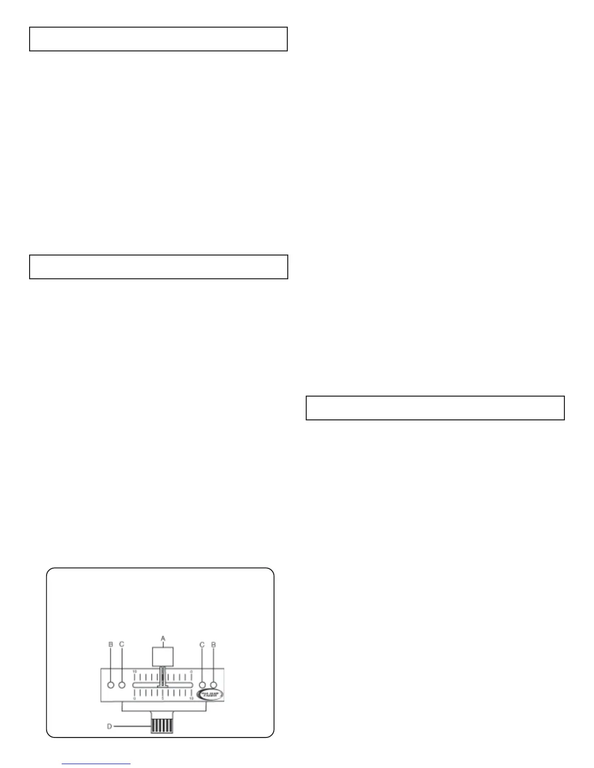
your Gemini dealer and follow these instructions:
1. Unscrew the outside FADER PLATE SCREWS (B). Do not
touch the INSIDE SCREWS (C).
2. Carefully lift the fader and unplug the CABLE (D).
3. Plug the new fader into the cable and place it back in the
mixer.
4. Screw the fader to the mixer.
The CROSSFADER CURVE SWITCH (28) allows you to adjust the kind
of curve the crossfader has. When the switch is in the left position,
the curve is gradual and gentle. When the switch is in the right
position, the curve is steep and cutting (perfect for scratching). The
CROSSFADER REVERSE SWITCH (26) allows you to reverse the
crossfader so that CHANNEL 2 is controlled by the left side of the
crossfader and CHANNEL 1 is controlled by the right side of the
crossfader.
NONO
NONO
NO
TETE
TETE
TE: When the
CRCR
CRCR
CR
OSSFOSSF
OSSFOSSF
OSSF
ADER REVERSE SWITADER REVERSE SWIT
ADER REVERSE SWITADER REVERSE SWIT
ADER REVERSE SWIT
CHCH
CHCH
CH
(26) (26)
(26) (26)
(26) is activated (moved to the right), only the crossfader
reverses. The Channel Slides, Gain, Kill Switches and tonal
controls do not reverse.
6. OUTPUT CONTROL SECTION: The level of the MASTER OUTPUT (1) is
controlled by the MASTER (21) control.
7. TALKOVER SECTION: The purpose of the talkover section is to allow
the program playing to be muted so that the mic can be heard above
the music. The MIC/TALKOVER (19) switch has three settings. When
the MIC/TALKOVER (19) switch is in the left position, the mic and
talkover are both off. When the MIC/TALKOVER (19) switch is in the
center position the mic is on, the MIC INDICATOR will glow, but
talkover is off. When the MIC/TALKOVER (19) switch is in the right
position, the mic and talkover will be on and the volume of all sources
except the Mic input are lowered by 16 dB. MIC LEVEL (20) controls
the level of the MIC.
8. CUE SECTION: By connecting a set of headphones to the PHONES
(36) jack, you can monitor either channel or both together. Move the
CUE SWITCH (25) to the left to monitor CHANNEL 1. Move the CUE
SWITCH (25) to the right to monitor CHANNEL 2. Move the CUE
SWITCH (25) to the center position to split the signals from each
channel so that CHANNEL 1 will be heard in one earphone and
CHANNEL 2 will be heard in the other earphone. Use the CUE LEVEL
(22) control to adjust the headphone volume without effecting the
overall mix.
9. DISPLAY: The DISPLAY (24) indicates the MASTER output.
Specifications
INPUTS:
DJ Mic..............................................................1.5mV 600 Ohm
Phono.........................................................................3mV 47Kohm
Line.......................................................................150 mV 27Kohm
OUTPUTS:
Amp.................................................................0 dB 1V 400ohm
Max..............................20V Peak to Peak
GENERAL:
Low (Channels 1 - 2)........................................................+ 12dB/-32 dB
Mid (Channels 1 - 2).........................................................+ 12dB/-32 dB
High (Channels 1 - 2).....................................................+ 12dB/-32 dB
Gain (Channels 1 - 2)...........................................................0 to -20dB
Frequency Response....................................20Hz - 20KHz +/- 2dB
Distortion................................................................................0.02%
S/N Ratio...............................................................better than 80dB
Talkover Attenuation..............................................................-16dB
Headphone Impedance.........................................................16ohm
Power Source........................................................115V/15V AC 7.5W
230V/15V AC 7.5W
Dimensions.......................................6.5” x 14” x 3” (165 x 355 x 85 mm)
Weight........................................................................................5 lbs (2.27 kg)
 Loading...