,167$//$7,21
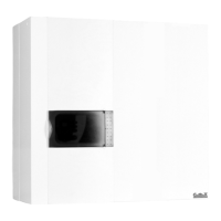
63$&(5%$&.3/$7(6833/,('$6$1237,21
The spacer back plate allows the pipes to be fed
through behind the boiler when they arrive from
above.
Assembly:
- Fit the angle mounting to the wall (supplied with
the boiler).
- Hang the spacer back plate on the angle mount-
ing.
- Hang the boiler on to the spacer back plate.
3/80%,1*&211(&7,216
Accessories to be connected:
- Expansion vessel (an option) precharged to
0.5 bar suitable for an installation up to 100 litres.
(For more than 100 litres provide for additional
expansion).
- Heating system safety pressure relief valve for
connecting to the waste water outlet via a funnel
and siphon trap.
- Condensate drainage siphon trap for connect-
ing via Ø 25 PVC pipe to the waste water outlet
via a funnel and siphon trap. When installing the
system, don’t forget to fill the siphon traps with
water before commissioning. These should be in-
spected twice a year.
-A circulating pump with an air vent. The silicon
tube from the purger should be slid inside the fun-
nel.
The heating flow and return pipes must be fitted with
stop valves so that work can be carried out on the
boiler if required without draining the installation.
:DWHUIORZUDWHWKURXJKWKHKHDWH[FKDQJHU
The power delivered by the boiler depends on the
water flow rate through the exchanger. This can be
set to between 1200 and 2500 litres/hour according
to the installation’s rated power output.
To ensure that heat transfer operates correctly and
to avoid any risk of boiling, never use a flow rate of
less than 1200 litres/hour.
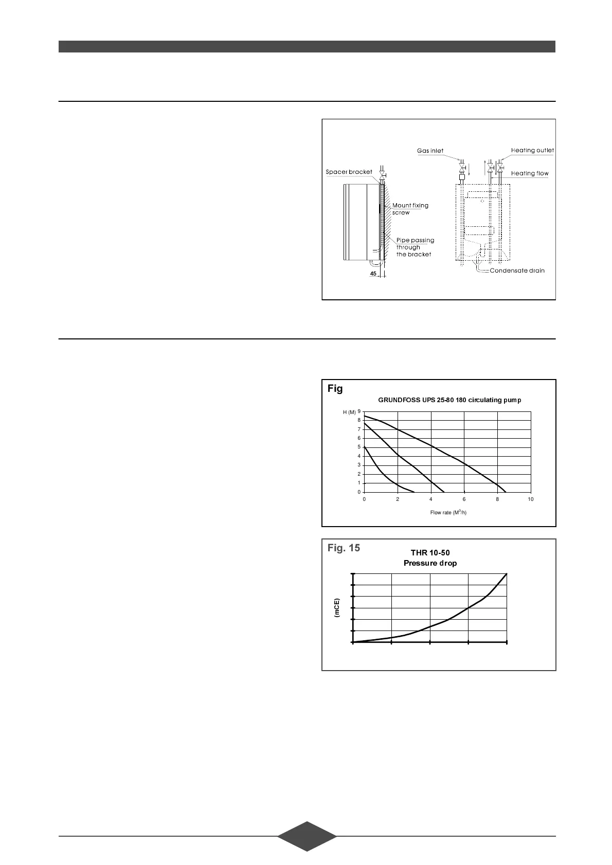
3UHVVXUHIORZUDWHFXUYHV
)LJ
*581')266836FLUFXODWLQJSXPS
0
1
2
3
4
5
6
7
8
9
0246810
Flow rate (M
3
/h)
H (M)
)LJ
7+5
3UHVVXUHGURS
0
1
2
3
4
5
6
0 500 1000 1500 2000
Flow rate (dm
3
/ h)
P
&
(
)LJ
 Loading...