Transfer Switch Installation Guidelines 5
Section 2 Installation
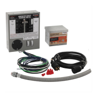
2.1 — Contents
What is Included in this Carton:
• Manual Transfer Switch with Utility and Generator main breakers mechanically interlocked preventing utility and
generator from powering the load at the same time
• Hardware Kit (including Bonding Screw and Label to convert switch to Service Entrance rating)
• Documentation: Installation Manual and Product Registration card
2.2 — Required Tools
2.2.1— Tools and Items Needed for Installation:
• Safety eye goggles
• 1/4” and 11/32” nut drivers
• Straight blade and Phillips screwdriver
• Electric drill and drill bits
• Wire cutter/stripper
• NEW 2-pole, 60 Amp or 100 Amp 125/250V circuit breaker to install in main load center (see Table 1) manufactured by
same as main load center
• Appropriately sized conduit, fittings, lock nuts and wire
• Anchors and screws to mount transfer switch to wall
2.2.2— Optional Items for Installation:
• Power Inlet Box that mounts outside for convenient generator connection to transfer switch
• Power Cord to connect generator to transfer switch via the power inlet box
2.3 — Specifications
Table 1: SPECIFICATIONS
Model 6333 6334
Max Generator Size in Watts (continuous) 15000 watts 25000 watts
UTILITY MAIN breaker, 1 Included, 1 additional
required
60 Amp 100 Amp
GEN MAIN breaker, included 60 Amp 100 Amp
NEMA Type Enclosure NEMA 1 NEMA 1
Max 1-pole Circuits / Max 2-pole Circuits NO PROVISION FOR BRANCH
CIRCUIT
NO PROVISION FOR BRANCH
CIRCUIT

 Loading...