Owner’s Manual for Portable Generator 5
Section 2 General Information and Setup
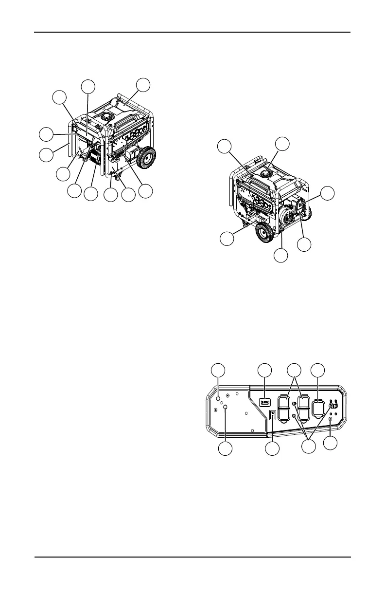
Figure 2-1. Features and Controls
Generator Components
Figure 2-2. Control Panel (Electric Start and
Idle Control) (if equipped)
13
14
20
12
10
8
7
6
11
5
16
15
19
4
013394
013395
23
24
25
1 120 Volt AC, 20 Amp, GFCI Duplex
Receptacle (NEMA 5-20R)
2 120/240 Volt AC, 30 Amp Locking
Receptacle (NEMA L14-30R)
3 Circuit Breakers (AC)
4 LP Regulator
5 Air Filter
6 Choke Lever
7 Fuel Tank
8 Grounding Lug
9 Stop/Run/Start Switch (if equipped)
10 Muffler
11 Handle
12 Gas Cap
13 Fuel Gauge
14 Oil Check/Fill
15 Recoil Starter
16 Fuel Shut Off (not shown)
17 Hour Meter
18 Battery Charger Input (if equipped)
19 Battery Location (if equipped)
20 Spark Arrestor
21 COsense RED (Hazard) (if equipped)
22 COsense YELLOW (Fault) (if equipped)
23 Fuel Selector Dial
24 LP Regulator Cover
25 Side Panel
21 1 2
22
3
013396
17
9
18

 Loading...


