4
SPECIFICATIONS
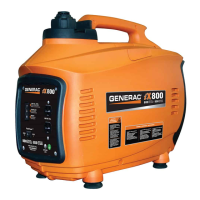
1600 WATT
Engine Type . . . . . . . . . . . . . . . . . . . . . . . . Single Cylinder, 4-Stroke
Engine Size . . . . . . . . . . . . . . . . . . . . . . . . . . . . . . . . . . . . . . . 99cc
Starter Type . . . . . . . . . . . . . . . . . . . . . . . . . . . . . . . . . . . . . . Recoil
Fuel Capacity/Type . . . . . . . . . . . . . . . . . . .0.69 Gal (2.6L)/Unleaded
Oil Capacity . . . . . . . . . . . . . . . . . . . . . . . . . . . . . . . . 0.63 Qt (0.6L)
Run time at 25% Rated Load . . . . . . . . . . . . . . . . . . . . . . 5.7 Hours
Spark Plug Type. . . . . . . . . . . . . . . . . . . . . . . . . . . . . NGK BPR7HS
Spark Plug Gap . . . . . . . . . . . . . . . . . . . . . . . . . . . . . . . . . . . ..030”
Dimensions L x W x H (in) . . . . . . . . . . . . . . . . . . . . . . 22 x 12 x 18
Weight Lb/kg . . . . . . . . . . . . . . . . . . . . . . . . . . . . . . . . . . 43.5/19.7
Maximum AC Output . . . . . . . . . . . . . . . . . . . . . . . . . . . . . . 1600W
Surge AC Output . . . . . . . . . . . . . . . . . . . . . . . . . . . . . . . . . 1650W
AC Volts. . . . . . . . . . . . . . . . . . . . . . . . . . . . . . . . . . . . . . . 120 VAC
Rated AC Current . . . . . . . . . . . . . . . . . . . . . . . . . . . . . . . . . .13.3 A
Frequency . . . . . . . . . . . . . . . . . . . . . . . . . . . . . . . . . . . . . . . 60 Hz
THD. . . . . . . . . . . . . . . . . . . . . . . . . . . . . . . . . . . . . . . . . . . . . 3.0%
Insulation Class . . . . . . . . . . . . . . . . . . . . . . . . . . . . . . . . . . Class B
Outlets. . . . . . . . . . . . . . . . . . . . . . . . . . . . . .(2) 5-15R, (1) 12 VDC
DC Volts. . . . . . . . . . . . . . . . . . . . . . . . . . . . . . . . . . . . . . . . 12 VDC
Rated DC Current. . . . . . . . . . . . . . . . . . . . . . . . . . . . . . . . . . . . 5 A
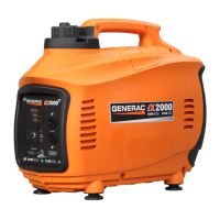
2000 WATT
Engine Type . . . . . . . . . . . . . . . . . . . . . . . . Single Cylinder, 4-Stroke
Engine Size . . . . . . . . . . . . . . . . . . . . . . . . . . . . . . . . . . . . . . 127cc
Starter Type . . . . . . . . . . . . . . . . . . . . . . . . . . . . . . . . . . . . . . Recoil
Fuel Capacity/Type . . . . . . . . . . . . . . . . . . 0.85 Gal. (3.2L) Unleaded
Oil Capacity . . . . . . . . . . . . . . . . . . . . . . . . . . . . . . . . 0.63 Qt (0.6L)
Run time at 25% Rated Load . . . . . . . . . . . . . . . . . . . . . . 5.3 Hours
Spark Plug Type. . . . . . . . . . . . . . . . . . . . . . . . . . . . . .NGK BPR6ES
Spark Plug Gap . . . . . . . . . . . . . . . . . . . . . . . . . . . . . . . . . . . ..030”
Dimensions L x W x H (in) . . . . . . . . . . . . . . . . . . . . . . 22 x 12 x 18
Weight Lb/kg . . . . . . . . . . . . . . . . . . . . . . . . . . . . . . . . . . 49.6/22.5
Maximum AC Output . . . . . . . . . . . . . . . . . . . . . . . . . . . . . . 2000W
Surge AC Output . . . . . . . . . . . . . . . . . . . . . . . . . . . . . . . . . 2200W
AC Volts. . . . . . . . . . . . . . . . . . . . . . . . . . . . . . . . . . . . . . . 120 VAC
Rated AC Current . . . . . . . . . . . . . . . . . . . . . . . . . . . . . . . . . .16.7 A
Frequency . . . . . . . . . . . . . . . . . . . . . . . . . . . . . . . . . . . . . . . 60 Hz
THD. . . . . . . . . . . . . . . . . . . . . . . . . . . . . . . . . . . . . . . . . . . . . 3.0%
Insulation Class . . . . . . . . . . . . . . . . . . . . . . . . . . . . . . . . . . Class B
Outlets. . . . . . . . . . . . . . . . . . . . . . . . . . . . . .(2) 5-20R, (1) 12 VDC
DC Volts. . . . . . . . . . . . . . . . . . . . . . . . . . . . . . . . . . . . . . . . 12 VDC
Rated DC Current. . . . . . . . . . . . . . . . . . . . . . . . . . . . . . . . . . . . 5 A
NOTE:
Power output and runtime are influenced by many factors,
some of which are fuel quality, ambient temperature and engine
condition. Output decreases approximately 3.5% for each 1,000
feet above sea level and 1% for every 10 degrees above 60°F.
EMISSIONS INFORMATION
The Environmental Protection Agency (EPA) requires that your
generator comply with exhaust emission standards. This generator
is certified to meet the applicable EPA emission levels. Additional
information regarding the requirements set by EPA is as follows:
The maintenance specifications provided in this manual must be
followed to ensure that your engine complies with the applicable
emission standards for the duration of the engine’s life. This engine
is certified to operate on gasoline. The emission control system on
your generator consists of the following:
• Fuel Metering System • Ignition System
– Carburetor – Spark plug
– Fuel Pump – Ignition module
– Fuel Lines • Exhaust System
• Air Induction System
– Intake pipe / manifold
– Air cleaner
The Emissions Compliance Period referred to on the Emissions
Compliance Label indicates the number of operating hours for
which the engine has been shown to meet Federal emission
requirements.
UNIT IDENTIFICATION (Figure 2)
1. Carrying Handle: Lift the generator by this handle only.
2. Spark Plug Cover: Allows access to the engine spark plug.
3. Primer Bulb: Used to prime the fuel system for starting.
4. Fuel Tank Cap: Access to fuel tank for filling.
5. Control Panel: location of generator controls and output
receptacles.
6. Air Intake Slats: Allows for cooling air to enter the housing.
7. Muffler: Lowers engine exhaust noise.
8. Choke: Cold engine starting aid
9. Left Side Service Cover: Allows access to air filter, fuel filter
and oil fill.
10. Vent Hoses: Hoses allow venting of the carburetor.
11. Fuel Shutoff: Controls fuel supply to the carburetor.
12. Starter Rope: Pull rope for starting engine.
CONTROL PANEL (Figure 3)
13. LOW OIL LEVEL LED (yellow): Lights up when oil level is
below safe operating level and the engine shuts down.
14. OVERLOAD LED (red): This LED indicates a system overload.
This LED should be used in conjunction with the READY LED
which will flash an error code, see No. 15.
15. READY LED (green): Indicates output from the generator
unless there is a low oil or overload condition. In the event of
a system overload the Ready LED will provide an indication
of the overload condition. The indication consists of a series
of flashes separated by a pause. These indications are as
follows:
1 Flash = Low Voltage. The unit has been overloaded to the
point where the output voltage has dropped to less
than 100V AC.
General Information
 Loading...