Installation
8 Automatic Transfer Switch Owner’s Manual
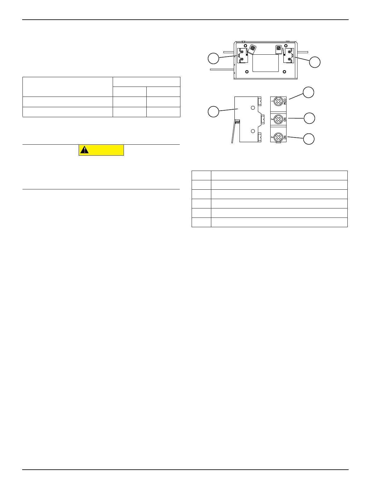
Connecting Auxiliary Contacts
If desired, there are Auxiliary Contacts on the transfer
switch to operate customer accessories, remote advisory
lights, or remote annunciator devices. A suitable power
source must be connected to the common terminal (D).
See Figure 3-1.
Contact operation is shown in the following chart:
NOTE: Auxiliary Contacts are rated 10 amps at 125 or
250 volts AC.
Figure 3-1. Auxiliary Contacts
Switch Position
Utility Standby
Common to Normally Open Open Closed
Common to Normally Closed Closed Open
(000134a)
CAUTION
Equipment damage. Exceeding rated voltage
and current will damage the auxiliary contacts.
Verify that voltage and current are within specification
before energizing this equipment.
A Auxiliary Contact (Actuated)
B Auxiliary Contact (Non-Actuated)
C Single Contact (Utility Position)
D Common Terminal
E Normally Open Terminal
F Normally Closed Terminal
 Loading...