EasyManuals Logo
Home>Generac Power Systems>Switch>RTSW200K3

Generac Power Systems RTSW200K3 User Manual

Generac Power Systems RTSW200K3
32 pages
To Next Page IconTo Next Page
To Previous Page IconTo Previous Page
Page #22 background imageLoading...
Page #22 background image
Drawings and Diagrams
18 Automatic Transfer Switch Owner’s Manual
Schematic Diagram
100-200A 240VAC (Drawing 0L2832, Sheet 1 of 2)
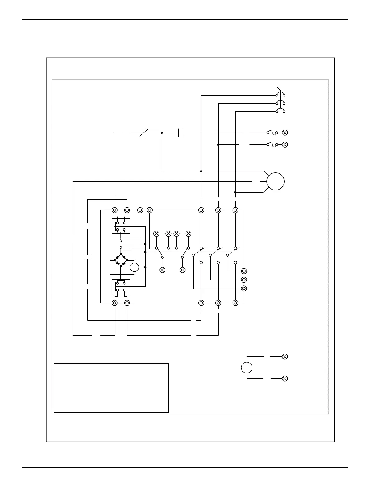
LS1,LS2,LS3 - LIMIT SWITCHES, ACTUATOR
PM - POWER MONITOR, 3 PHASE UTILITY
TS - TERMINAL STRIP (CUSTOMER CONNECTION)
TR - RELAY, TRANSFER
F1,F2 - FUSE 5A SENSING
1.) ALL CONTACTS SHOWN WITH
TRANSFER SWITCH IN UTILITY
POSITION.
B2A2
ATS - TRANSFER SWITCH CONTACTOR
C - CONTACTOR ACTUATING COIL
N2A
LEGEND
TR
E1
4
6
N2A
205
LS2
WHITE
C
RED
LS3
LS1
A1 B1
T1
126
126
5
1
TR
TR
E1
E2
E1
7
NOTES:
8
E2
1
ATS
4
523
T2
6
194
23
194
23
N1B
1
N2A
N1B
PM
8
N2A
N1A
PM
4
N2A
5
3
F1
F2
N2
N1
UCB
N3
UCB - UTILITY CIRCUIT BREAKER
GROUP G
SCHEMATIC - DIAGRAM
100-400 AMP 240VAC
DRAWING #: 0L2832
REVISION: "A"
DATE: 08/25/15
001257

Table of Contents

Questions and Answers:

Question and Answer IconNeed help?

Do you have a question about the Generac Power Systems RTSW200K3 and is the answer not in the manual?

Generac Power Systems RTSW200K3 Specifications

General IconGeneral
BrandGenerac Power Systems
ModelRTSW200K3
CategorySwitch
LanguageEnglish

Related product manuals