Installation
10 Automatic Transfer Switch Owner’s Manual
Connecting Power Source and
Generator Power Supply
Installation and interconnection diagrams are provided in
this manual.
NOTE: All installations must comply with national, state
and local codes. It is the responsibility of the installer to
perform an installation that will pass the final electrical
inspection.
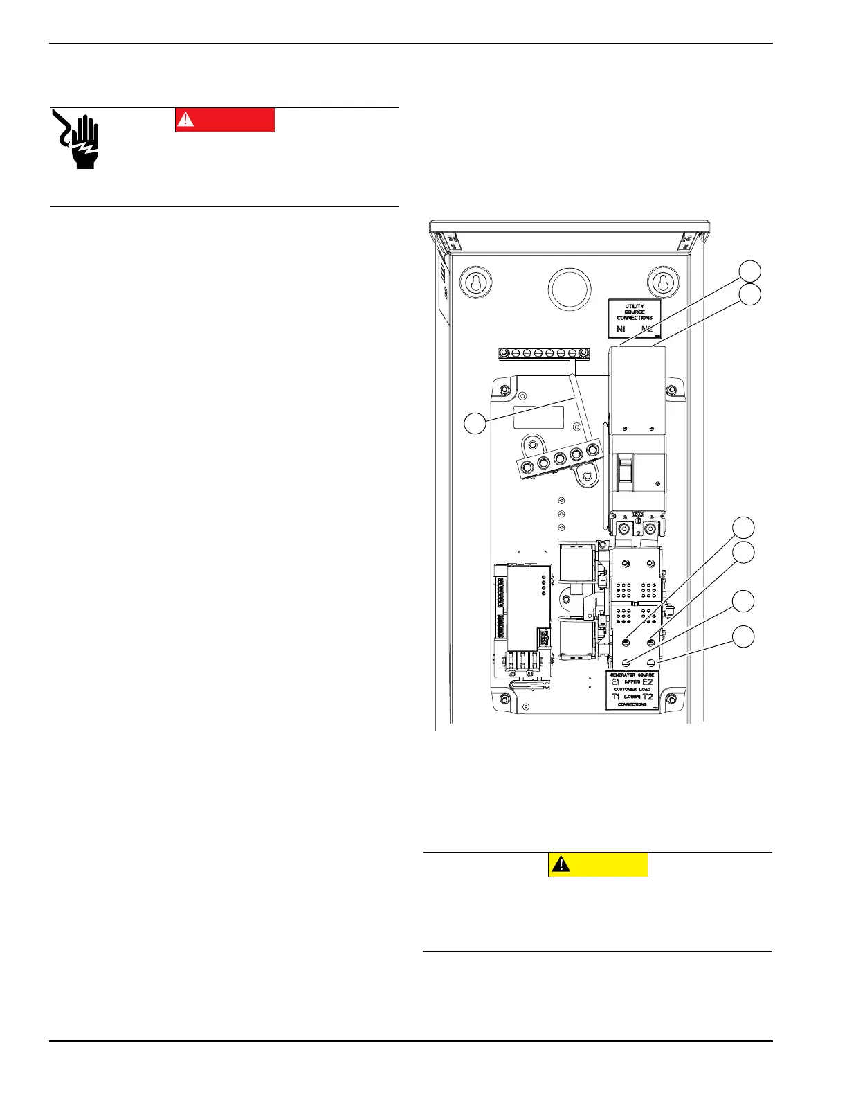
1. Connect utility supply at the utility service
disconnect circuit breaker terminals N1 and N2.
Follow torque specifications listed on the circuit
breaker.
2. See Figure 3-2. Connect utility neutral and ground
to the Upper Neutral and Ground terminals. Neutral
and Ground terminals are bonded to each other
with a jumper wire (A).
NOTE: Neutral to Ground jumper wire (A) is
provided for use if required by local codes.
3. Connect generator to the generator terminals (E1
and E2) on the transfer mechanism.
4. Connect the generator neutral wire to the lower
neutral lug.
IMPORTANT NOTE: A jumper wire (B) bonds
the upper and lower Neutral lugs. NEVER
remove this wire.
5. Connect a subpanel supply to lower T1 and T2
Terminals. Connect subpanel Neutral and Ground
to lower Neutral and Ground bars.
Conductor sizes must be adequate to handle the
maximum current to which they will be subjected, based
on the 75°C column of tables, charts, etc. used to size
conductors. The installation must comply fully with all
applicable codes, standards and regulations.
Knockouts into the transfer switch can be made in the
field as needed for entry of power cables and conduit.
Conduit entry shall maintain the proper wire bending
spaces required by Tables 312.6 (A) and (B) in the NEC.
Conduits should be arranged to provide separation
between the Utility and Generator supply conductors
inside the enclosure.
For transfer switches installed in wet locations, power
cables or conduits entering above the level of
uninsulated live parts shall use fittings listed for use in
wet locations as required by 312.2 in the NEC.
NOTE: If aluminum conductors are used, apply corrosion
inhibitor to conductors. After tightening terminal lugs,
carefully wipe away any excess corrosion inhibitor.
Figure 3-2. Wiring Connections
Tighten terminal lugs to the torque values as noted on the
decal located on the inside of the door. After tightening
terminal lugs, carefully wipe away any excess corrosion
inhibitor.
Electrocution. Turn utility and emergency
power supplies to OFF before connecting
power source and load lines. Failure to do so
will result in death or serious injury.
(000116)
DANGER
(000120)
CAUTION
Equipment damage. Verify all conductors are tightened
to the factory specified torque value. Failure to do so
could result in damage to the switch base.
 Loading...