AD J USTING BELT TENSION
1. REMOVE UPPER ACCESS PANEL: Remove all ¼” bolts holding the Upper
access panel with a 3/8” socket and ratchet. The panel is sealed with Loctite 598
High Performance RTV Silicone Gasket Maker. The panel will need to be pried
from the frame with a large screwdriver.
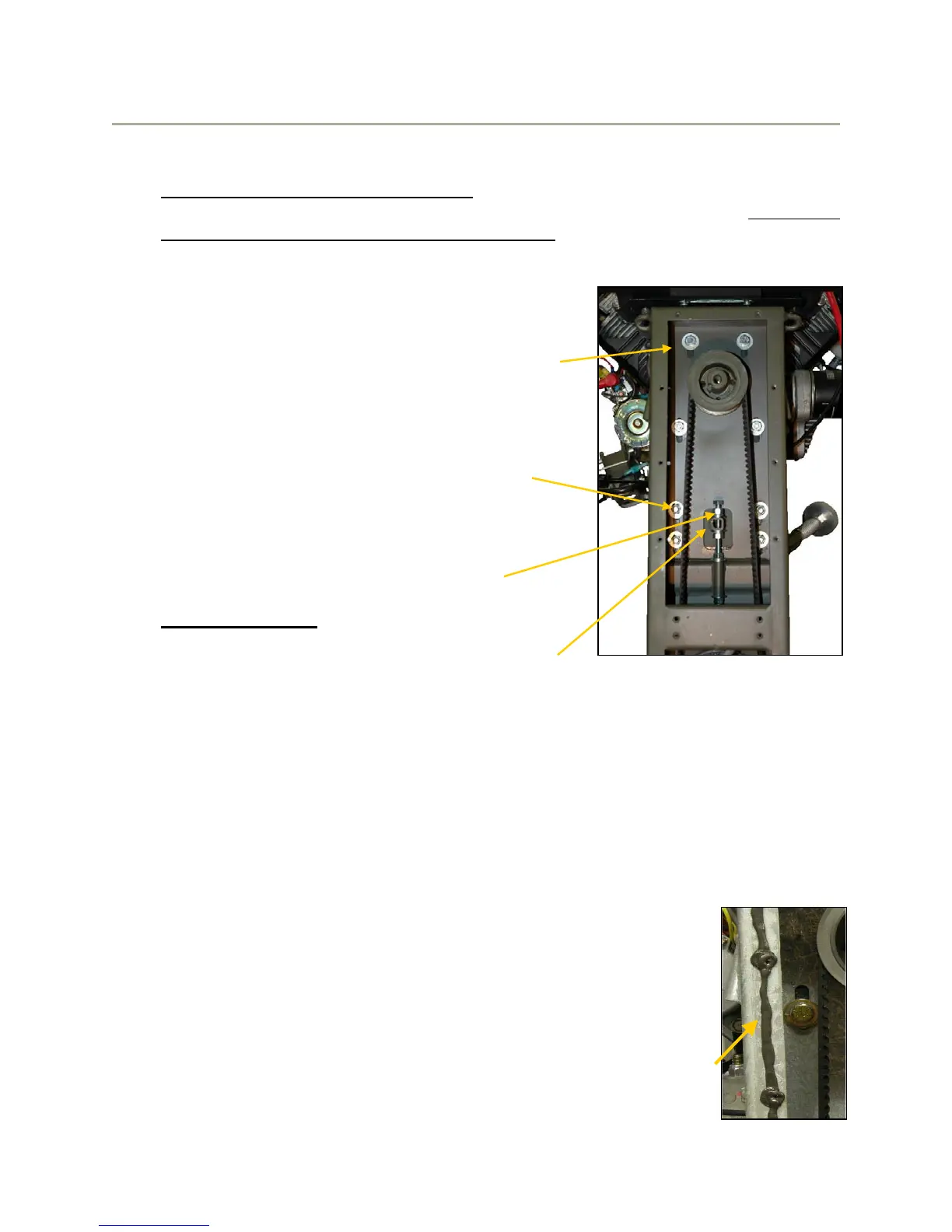
2. Locate the 3/8” bolts shown in the photo to the
right. Using a 9/16” socket, ratchet and extension,
loosen the top 4 bolts around the engine
crankshaft. Hand tighten the bolts to allow the
frame to slide up and down but remain against the
engine.
3. Loosen the lower 4 bolts using the ratchet and
9/16” wrench. Snug the bolts as done for
the upper bolts to allow the frame to slide
up and down.
4. Loosen the Upper Tension Adjustment nut on the
jack bolt using a 9/16” open end wrench.
5. NEW BELT ONLY - If installing a new belt, loosen
the Lower adjustment nut and turn the Upper
adjustment nut clockwise to loosen the belt.
Remove all four of the 3/8” bolts securing the sprocket shaft bearing housing
shown on page 12. The sprocket unit can then be lifted enough to change the
belt. Apply Blue Loctite to bolts and reinstall them with the new belt in place
around the sprocket. Torque all four bolts to 250 In.-Lbs. (21 Ft.-Lbs.)
6. To increase belt tension, turn the Lower Tension Adjustment nut counterclockwise
until the proper tension is achieved as indicated by the tension gauge instructions
listed on page 14.
7. Tighten all 8 of the 3/8” bolts shown above to 250 In.-Lbs. (21 Ft.-Lbs.)
8. Tighten the Upper Tension adjustment nut.
9. After tightening all bolts and nuts listed above, check belt tension
again and readjust if necessary using the same procedures.
Replace the inspection hole plug when finished.
10. Remove existing RTV Silicone from frame and access panel and
insure that mating surfaces are clean. Apply a continuous 1/8”
bead of silicone to the frame surface and inside the bolt holes.
Ensure that the bead is continuous around the perimeter to
 Loading...