6
Power Limit Solution for Grid-Tied PV Inverters User Manual V1.0-2022-09-15
Inverter I
Router
Monitoring
System
Inverter N
Load
Utility Grid
Meter
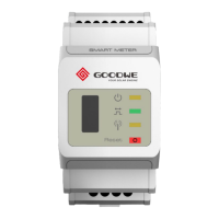
GM3000C
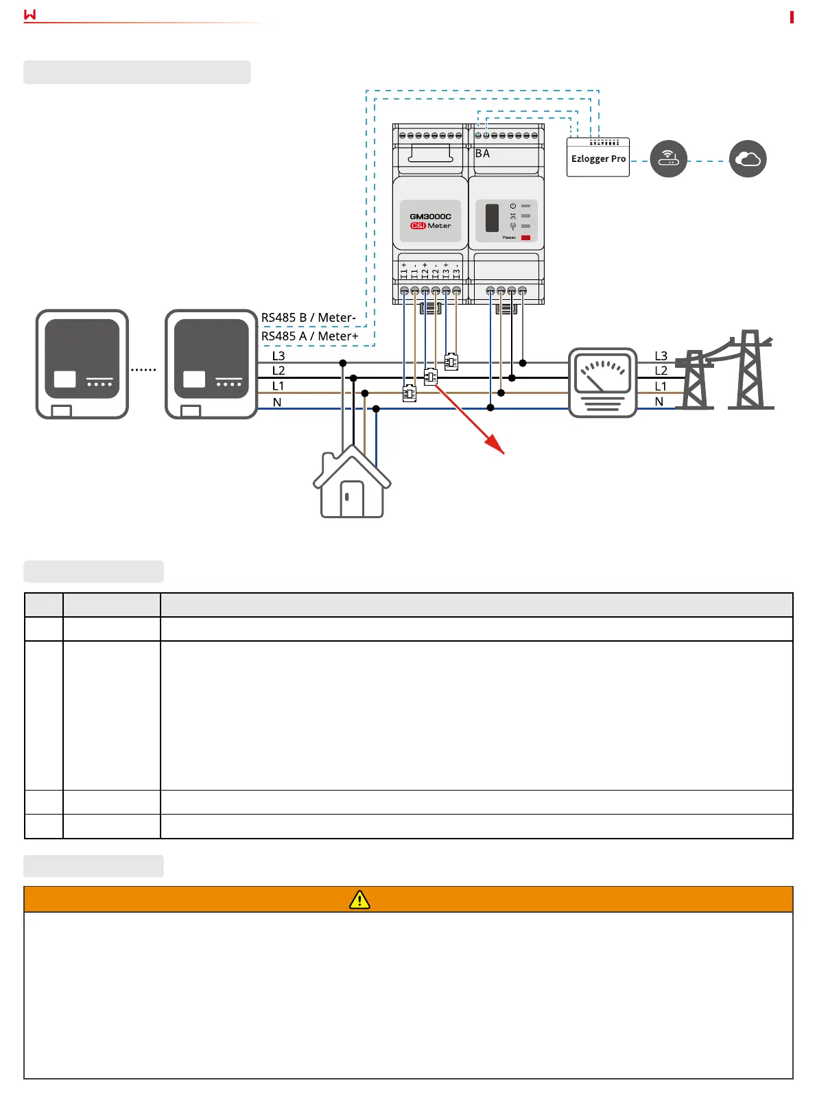
System with Multiple Inverters
External CT
No. Parts Description
1 Inverter Applicable inverters are SDT G2 series, SMT series, MT series and HT 1100V series.
2 GM3000C Prepare CT by yourself for external installation when selecting 3000C smart meter in networking.CT
Specication:
1. Choose nA/5A for the current transformation ratio of the external CT. (n refers to CT primary input
current value, which is between 200 - 5000, chosen by the user according to the actual conditions. 5A
refers to CT secondary output current value.)
2. The sampling error for the CT current shall be ≤ 1% (the recommended precision is 0.5, 0.5s, 0.2, or 0.2s).
3. The recommended wire diameter for the CT secondary output cable is 1.5mm, corresponding to 1.5mm²
in cross-sectional area.
3 EzLogger Pro Install an EzLogger Pro in systems with multiple inverters for power limit function.
4 Load The load current of any phase shall be more than 120A.
WARNING
1. The place to snap t the CT shall be near the Grid-Tied entry point. Make sure the connecting direction is right. If CT is installed
reversely, it is unable to realize the power limit function.
2. The appearances of the inverter and its communication port for CT connection vary according to dierent types. Please refer to
the related inverter’s user manual or quick installation guide for specic CT wiring.
3. The CT bore diameter shall be bigger than the outer diameter of AC power cable, to ensure the AC power cable can be inserted
into CT.
4. For specic CT wirings, please refer to the documents provided by the respective manufacturer, to ensure that the wiring
direction is correct and CT is able to work properly.
5. CT shall be snap tted on Cable L1, L2 and L3. Do not t it on Cable N.
Wiring Description
Parts Description
 Loading...