8
Power Limit Solution for Grid-Tied PV Inverters User Manual V1.0-2022-09-15
• Non-MT Series and Non-SMT Series Inverters;
• Inverters with LCD;
• Inverters nished wiring and power on.
Preconditions
Operations for Inverters with LCD
Steps
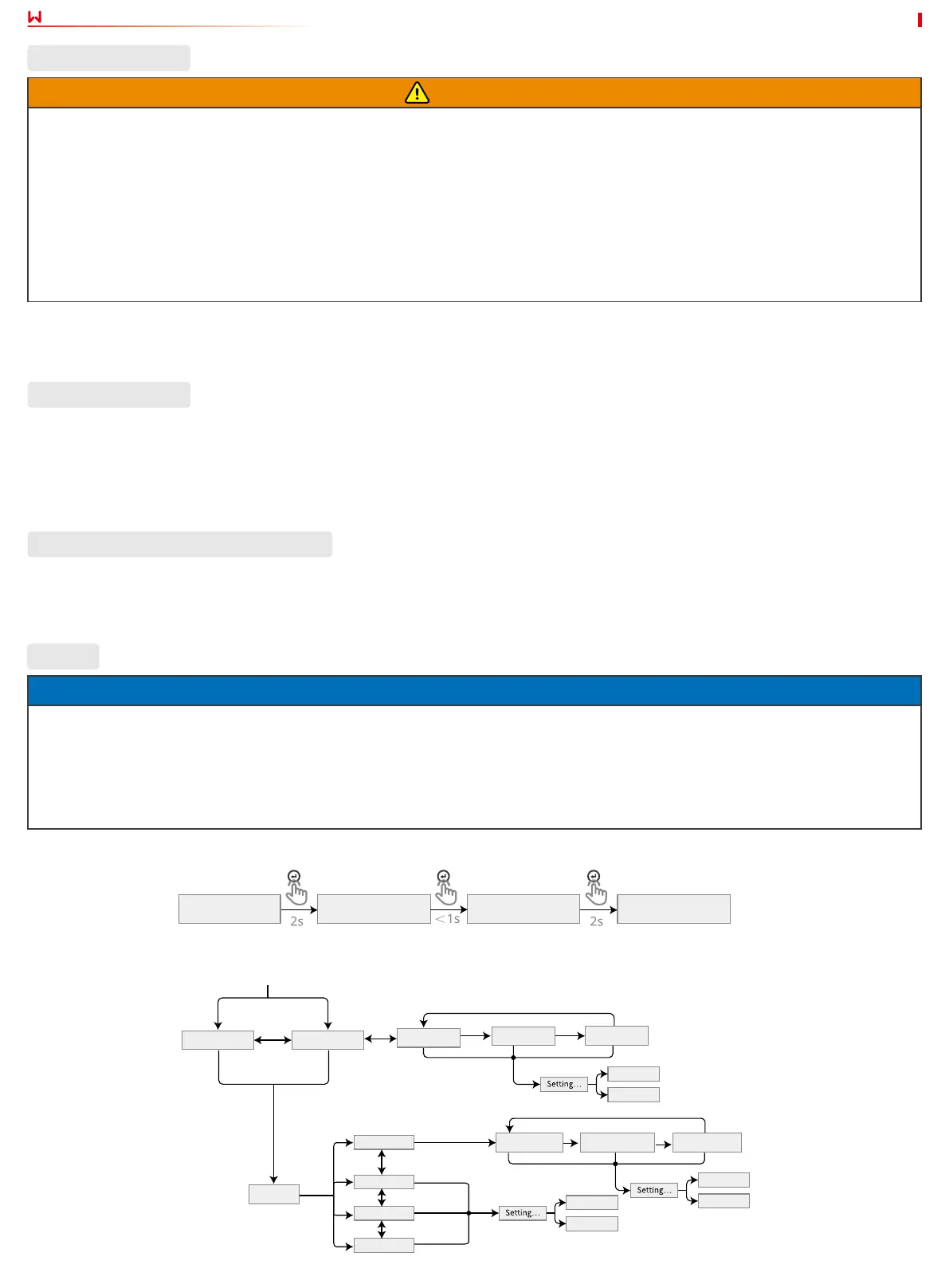
3 Parameter Setting
3.1 Setting Power Limit Parameters via LCD
• Stop pressing the button for a period on any page, the LCD will get dark and go back to the initial page.
• Short press the button to switch menu or adjust parameter values.
• After adjusting the parameter values, long press the button, and the parameters will be set successfully; enter into the sub menu.
Notice
• Below User Interface (UI) gures in this document are from DNS series inverters with rmware version V1.00.00 and communication
version V1.00. The screenshots are for reference only. For detail information, please nd in the related inverter’ user manual to
set the parameters.
• The name, range, and default value of the parameters are subject to change or adjust. The actual display prevails.
• The power parameters should be set by professionals, to prevent the generating capacity from being inuenced by wrong
parameters.
Step 1 (Optional) Set the safety country/region in compliance with the local grid standards and application scenario of the inverter.
Step 2 Short press the buttons on the LCD till “Set the power limit value” appearing.
Step 3 Set the “power limit value” according to the power value which is actually able to feed back into the utility grid.
WARNING
1. Connect SEC1000 AC cable to a 3L/N/PE Grid. The voltage of the Grid shall be within allowable voltage sampling scope of
SEC1000.
2. The place to snap t the CT shall be near the Grid-Tied entry point. Make sure the connecting direction is right. If CT is installed
reversely, it is unable to realize the power limit function.
3. The appearances of the inverter and its communication port for CT connection vary according to dierent types. Please refer to
the related inverter’s user manual or quick installation guide for specic CT wiring.
4. The CT bore diameter shall be bigger than the outer diameter of AC power cable, to ensure the AC power cable can be inserted
into CT.
5. For specic CT wirings, please refer to the documents provided by the respective manufacturer, to ensure that the wiring
direction is correct and CT is able to work properly.
6. CT shall be snap tted on Cable L1, L2 and L3. Do not t it on Cable N.
If none of the above conditions can be satised, no EzLogger Pro or SEC1000 applied in the system as well, you can set the related
parameters via SolarGo App.
Wiring Description
Short press
Short press
Short press
Short press
Short press
Short press
Short press
Short press
Long press for 2s
Long press for 2s
Long press for 2s Long press for 2s
Long press for 2s
Long press for 2s
Long press for 2s
Long press for 2s
Long press
for 2s
Long press for 2s
Long press for 2s
Long press for 2s
Long press for 2s
Shadow MPPT ON
Pac = xxx W
Shadow MPPT OFF
Pac = xxx W
Power Limit
Pac = xxx W
Set OK
Set Fail
Time Interval
010 min
Time Interval
010 min
Time Interval
010 min
Soft Limit ON
Set Power Limit
XX%
Set Power Limit
XXX%
Set Power Limit
X
X
X
X%
Set OK
Set Fail
Set OK
Set Fail
Soft Limit OFF
Hard Limit ON
Hard Limit OFF
Wait
Wait
Wait
Select Country /
Region
Country code 1
Country code 1
Normal
Pac=XXX.XX W
 Loading...