Combi V3, Combi Max and Vortex Combi models
46
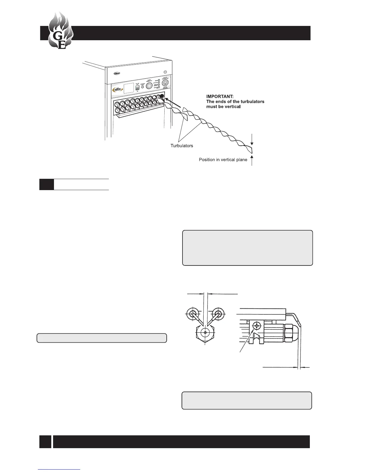
Fig. 32
IMPORTANT: The electrode settings given above
MUST be observed
4 ± 0.3 mm
Clamp screw
2 to 2.5 mm (Combi 70 V3)
3 to 3.5 mm (Combi 90 V3, Combi Max
and Vortex Combi)
Cleaning the burner
10.4
10 - BOILER SERVICING
Fig. 31 Vortex Combi turbulators
See Section 14.1
1 Combustion head - Loosen the two screws securing
the combustion head to the burner flange and withdraw
the head. Clean and refit the combustion head.
2 Inspect the ignition electrodes - With the combustion
head removed, loosen the electrode clamp screw and
withdraw the electrode assembly. Wipe clean and
check for any cracks in the ceramic insulation. Replace
if necessary.
Check the electrode settings - Electrode tips
approximately 4 mm apart and 2 to 2.5 mm
(Combi 70 V3) or 3 to 3.5 mm (Combi 90 V3,
Combi Max, Vortex Combi) in front of the
nozzle, see Fig 32.
3 Nozzle - The nozzle should be replaced on an
annual service.
Check that the nozzle fitted is the correct size and
type , refer to tables in Section 4.3, 4.4 or 4.6 and
boiler data label.
Do NOT attempt to clean the nozzle.
Remove and replace the nozzle using a good fitting
spanner (16 mm). The use of an ill-fitting spanner will
damage the nozzle and could lead to an incorrect
flame pattern. Always check the electrode settings
after replacing the nozzle, see Fig. 32.
4 Photocell - The photocell is a push-fit in the burner
body. Carefully pull out the photocell to clean.
5 Fan - With the air intake spigot removed, remove the
screws securing the fan housing cover (R/H side of
burner) and remove the cover. Inspect the fan and
housing and clean as necessary. Replace the cover.
6 Pump filter - With the burner cover removed,
remove the four screws securing the pump end
cover. Remove the filter and wash in kerosene.
Replace the filter and end cover, ensure the 'O' ring
is in position.
To ensure safe and efficient operation of the boiler it
is important that re-commissioning is carried out,
especially combustion checks (CO
2
level, flue gas
temperature and smoke number) after the boiler has
been serviced.
Refer to the Commissioning instructions starting on
page 41.
 Loading...


