Section 2: Using your BoilerPage 6
HEATING SWITCH
When set to TIMED, the boiler will only provide central heating
when either the programmer or timer is in a ‘heating on’ period
and the room thermostat is ‘calling’ for heat.
When set to OFF, the boiler will not provide central heating at all.
When set to CONSTANT, the boiler provides central heating
continuously when the room thermostat is ‘calling’ for heat,
overriding all of the timer or programmer heating settings.
HOT WATER SWITCH
This switch allows the hot water operation of the boiler to be
manually switched o if hot water is not required. With the
switch set to OFF, the burner will not re to maintain the water
temperature in the store and the hot water (store) pump will not
operate.
If a two channel programmer is connected to the boiler (see
Option D in Section 1.1), when this switch is set to TIMED the
boiler will provide hot water only during the ‘on’ periods set on the
programmer.
When the switch is set to CONSTANT the boiler provides hot
water continuously on demand, overriding any programmer
settings.
Refer to Section 2.5 for information on the ‘night time’ hot water
function present on Grant Vortex combi boilers.
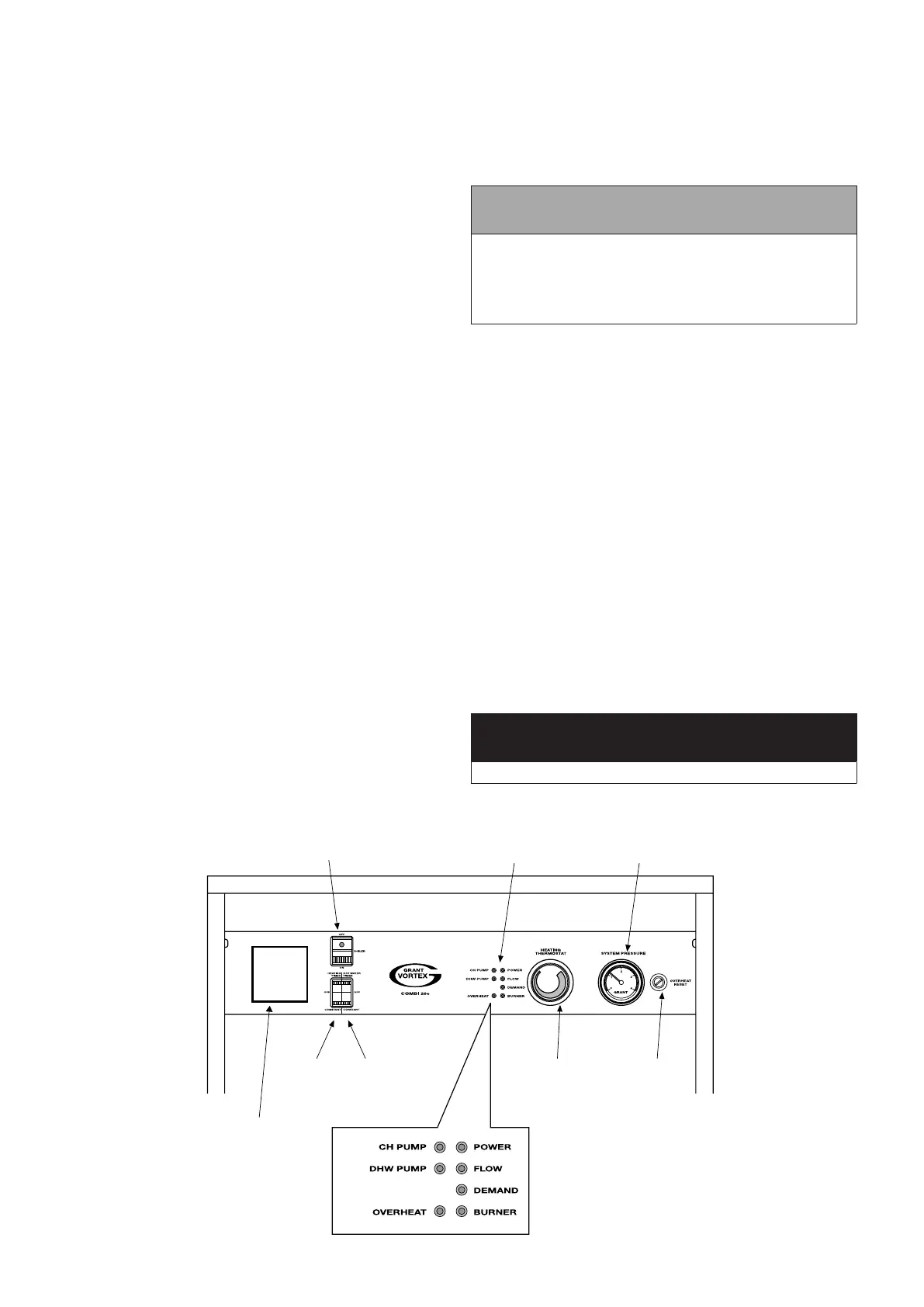
BOILER INDICATOR LIGHTS
These 7 red lights, located on the boiler control panel, indicate
the operating situation of the boiler. Refer to Figure 2-1 for the
position of these lights on the boiler control panel.
2.8 HEATING SYSTEM CONTROLS
TIMER (IF FITTED)
If a mechanical timer is tted, it will only control the times that the
boiler heats the central heating system (the heating switch on the
control panel must be set to TIMED). Hot water will be available
on demand (if the hot water switch on the boiler control panel is
set to CONSTANT).
A ‘plug-in’ mechanical timer is available to purchase from Grant
UK (part code: MTKIT), which ts into a suitably sized ‘knockout’
panel in the boiler control panel (see Figure 2-1).
PROGRAMMER (IF FITTED)
If a two-channel programmer is tted, it will control the times that
the boiler heats the central heating system and the times that
the boiler will provide instant hot water. Both the heating and hot
water switches (on the control panel) must be set to TIMED.
Refer to the manufacturer’s instructions supplied with your
programmer for further details.
ROOM THERMOSTAT
This thermostat allows you to control the room temperature at
which the boiler will re to provide central heating to your property.
The room thermostat is usually located in a downstairs area such
as a hallway or living area.
If your heating system is ‘zoned’ you will have more than one
room thermostat, with each thermostat controlling the temperature
of a separate heating zone.
! NOTE !
For your boiler to operate to provide you with heating,
the programmer (or timer) must be in an ‘ON’ period for
heating AND the room thermostat must be ‘calling’ for heat.
The heating switch on the control panel must also be set to
TIMED (if a timer or programmer is tted) or ON.
THERMOSTATIC RADIATOR VALVES
Your heating system may also include Thermostatic Radiator
Valves (or TRVs). If you have them, they will be tted on some or
all of your heating system radiators.
A TRV is a self-regulating valve, i.e. not connected to the
other heating system controls, such as a programmer or room
thermostat, and is designed to regulate the temperature in the
room in which it is situated.
A TRV senses the air temperature around it and controls the
water ow to the radiator on which it is tted to regulate its heat
output to the room. The head of the TRV can be rotated to set it to
give the required room temperature. Once correctly set, it should
ideally be left in that position and not used as an on/o control for
the radiator.
As the correct operation of a TRV is based on it sensing the air
temperature of the room it is tted in, take care not to cover the
TRV head (with curtains, furniture etc).
Refer to the manufacturer’s instructions supplied with any TRVs
tted to your heating system for further details.
2.9 ELECTRICITY SUPPLY
The boiler requires a 230/240 V AC 50 Hz supply. It must be
protected by a 5 Amp fuse.
! WARNING !
The electrical connections to the boiler must be earthed.
Heating
switch
Hot water
switch
Boiler
thermostat
Over heat
reset (under
black cap)
Boiler
On / Off switch
(with ‘mains on’
neon)
Indicator
lights
Pressure
gauge
‘Knock-out’
panel for Grant
‘plug-in’ timer
Figure 2-1: Vortex combi boiler control panel
 Loading...


