EN - 13
UNIT ASSEMBLY
Package Contents
Unit, Mower Deck and Literature Pack
Preparation Checklist
Refer to the Owner/Operator manual as
required.
1. Unpack Unit – Remove shrink wrap and
packaging materials.
2. Remove Unit From Container – Open
Bypass Valves (dump valves) (See
Moving the Unit with the Engine Off on
page 21).
Push unit from container onto a level
surface. Close the bypass valves.
3. Tires – See SPECIFICATIONS on
page 38.
4. Seat – See Seat Adjustments on
page 18.
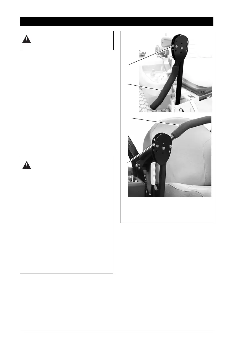
5. Position Steering Levers – Remove
spacers and rotate steering levers to the
operating position. Reinstall spacers.
Tighten hardware securely (Figure 3).
6. Rollover Protection Structure (ROPS) –
raise center bar (see Rollover Protection
Structure (ROPS) on page 18).
7. Battery – Remove battery from unit and
charge (See Battery on page 27).
8. Check Engine Crankcase – Check and
add oil if needed. See Engine Manual for
specifications.
9. Fill Engine Fuel Tank – Add clean fuel to
the fuel tank. DO NOT OVERFILL! See
Filling Fuel Tank on page 19.
IMPORTANT: Refer to Engine Manual for fuel
type.
10. Hardware – Check for loose hardware.
ASSEMBLY
WARNING: AVOID INJURY. Read
and understand entire Safety
section before proceeding.
CAUTION: Avoid injury! Explosive
separation of tire and rim parts is
possible when they are serviced
incorrectly:
• Do not attempt to mount a tire
without the proper equipment
and experience to perform the
job.
• Do not inflate the tires above the
recommended pressure.
• Do not weld or heat a wheel and
tire assembly. Heat can cause an
increase in air pressure resulting
in an explosion. Welding can
structurally weaken or deform
the wheel.
• Do not stand in front or over the
tire assembly when inflating. Use
a clip-on chuck and extension
hose long enough to allow you to
stand to one side.
Figure 3
1. Steering Lever in Shipping Position
2. Spacers
3. Steering Lever in Operation Position
1
2
3
2
 Loading...