GB - 11
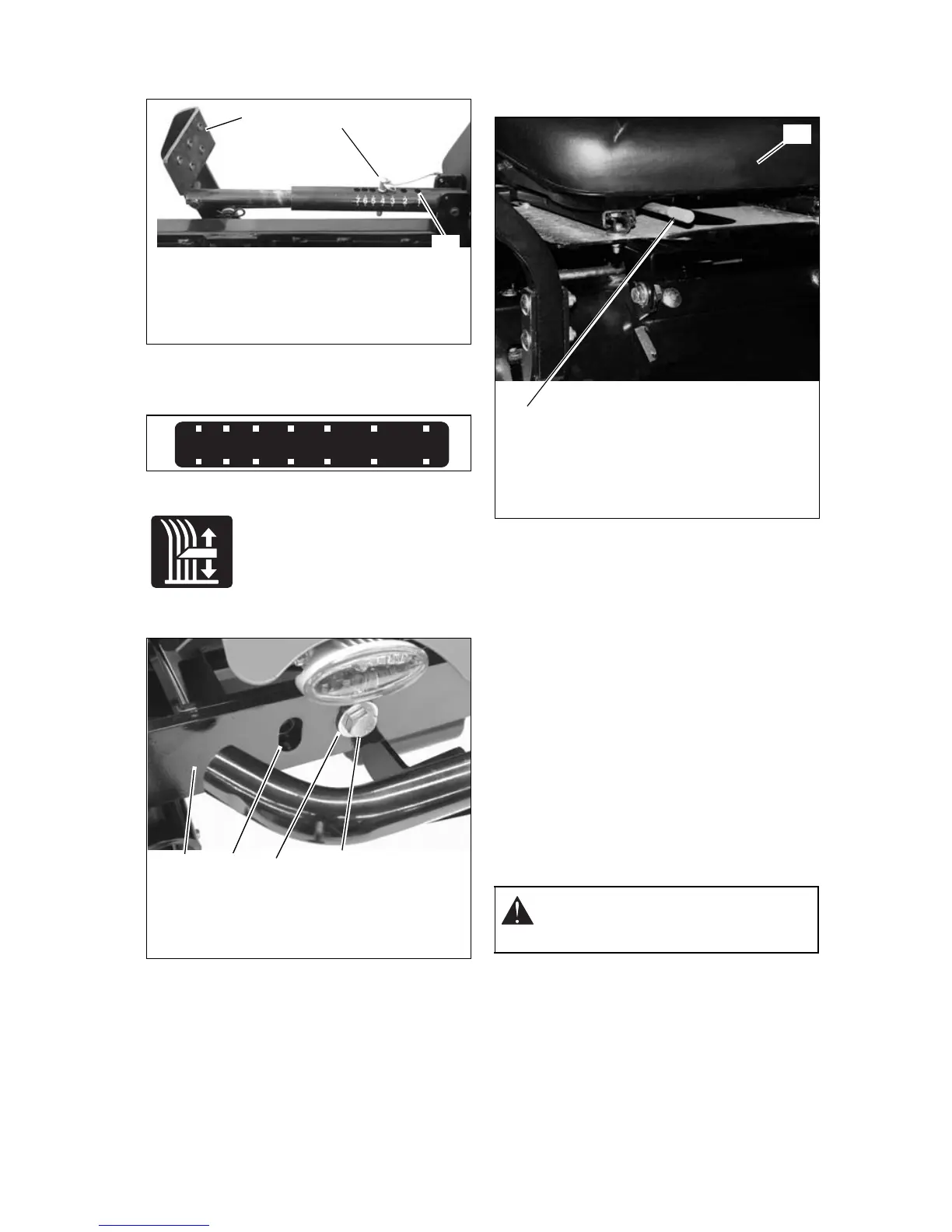
Mower Lift Pedal (Figure 5)
Raises and lowers mower deck.
NOTE: The adjustment pin is used to set the
height of the mower deck. See
SPECIFICATIONS on page 26 for cutting
height dimensions.
Press mower lift pedal and install adjustment
pin in the desired adjustment hole.
NOTE: Adjusting the seat
further forward will help
increase the leverage in lifting
the mower deck (see Adjusting
Seat on page 11).
Axle Locks (915078, 080, 082)
(Figure 6)
NOTE: The unit comes shipped with the front
axle in the lockout position.
If a pivoting front axle is needed: Remove
axle lock hardware from lockout position and
install axle lock hardware in pivoting position
on both sides of front axle.
NOTE: To lock front axle, install axle lock
hardware in the lockout position on both sides
of the axle.
Adjusting Seat
Lift adjustment lever and slide seat forward or
backward to the desired position.
FILLING FUEL TANKS
1. Clean fuel caps and surrounding area to
prevent dust, dirt, and debris from
entering fuel tanks.
2. Remove fuel caps.
IMPORTANT: See Engine Manual for correct
type and grade of fuel.
3. Fill fuel tanks to 2-1/2 in. (6.35 cm) below
bottom of filler neck. See
SPECIFICATIONS on page 26 for
capacity of fuel tanks.
4. Replace fuel caps.
STOPPING IN AN EMERGENCY
Bring steering levers back to neutral, set
parking brake, and turn off engine.
MOVING UNIT MANUALLY
Disengage (2) transmission bypass levers to
drive unit and engage (1) transmission
bypass levers to push unit manually
(figure 8).
OE0060
2
3
1. Adjustment Pin 2. Mower Lift
Pedal
3. Adjustment Hole
Figure 5
1
765 4 3 2 1
05304900
OE0090
08088400A
OE0240
43
2
1
1. Front Axle
2. Pivoting Position
3. Lockout Position
4. Axle Lock
Hardware
Figure 6
WARNING: DO NOT disengage or
bypass transmission and coast
downhill.
OE0151
2
1. Seat 2. Adjustment
Lever
Figure 7
1
 Loading...