15RD
1BK
2WH
5RD
÷_ 4RD
17BU
BK
HEATER
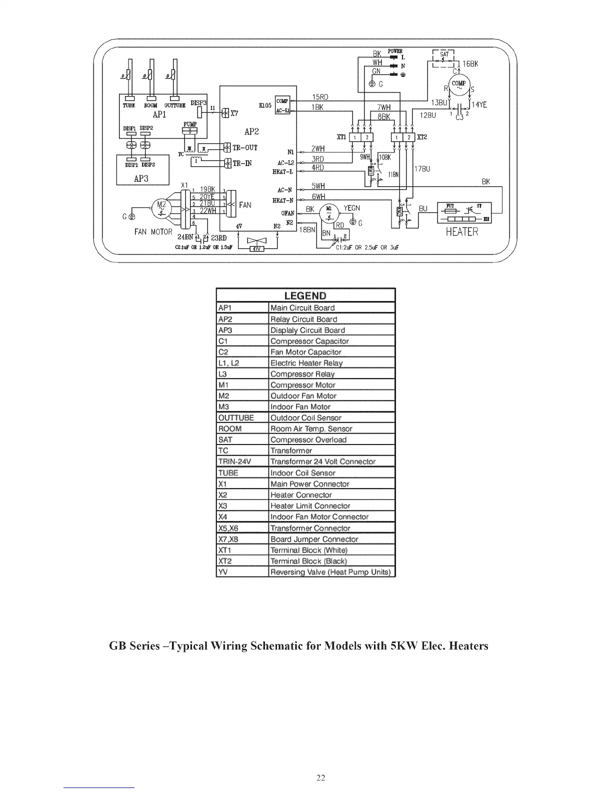
LEGEND
AP1 Main Circuit Board
AP2 Rei_uCircuit _ard
AP3 BisplaIy Circuit _ard
C! Compressor Ca_citor
C2 Pan Motor Capacitor
Lt, _ Eiectric H_ter Rei87
C£_£ressor Re_ay
M1
M2 Outdoor Pan Motor
M3 indoor Fan Motor
OU_UBE Outdoor Co_ Sensor
ROOM Room Air Temp. Sensor
SAT
TC Trar_former
TRiN,_24V Trar_lormer 24 VoR Conreetor
TUBE indoor Coit Sensor
X1 Main Power Conne_or
X2 Heater Oenne_or
X3 Heater Umit Con_etor
X4 tnd_r Fan Motor Conneclor
Transformer Co nne_or
X,_,X:8 Boa_d Jum£er Connec_or
_1 Terminai B©,ck tWhite}
XT2 Termini Biock
W R:_e_sing _e (Heat Pump Unils)
GB Series -Typical Wiring Schematic for Models with 5KW Elec. Heaters
22
 Loading...