Ducted Type Split Air-Conditioner Units(Inverter Series)
27
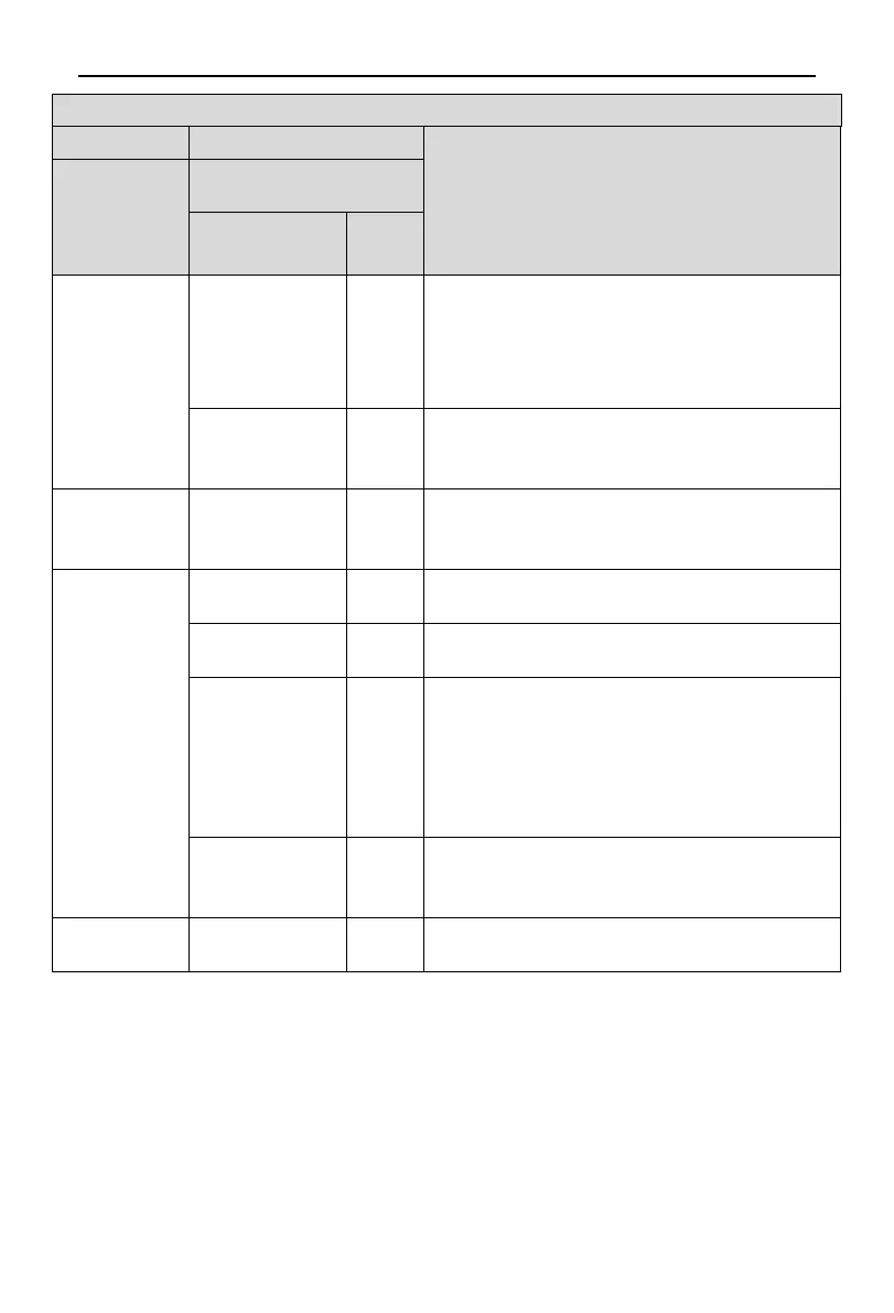
Description of each stage of debugging progress
Instruction for Code and Operating Method
Progress
LED
Display code
Display
status
07_ Component
inspection of
indoor unit
07/ Corresponding
error code
Display
repeatedly
Component error of indoor unit.
After eliminating all the errors, enter the next step
automatically, if the ODU should be powered off for
troubleshooting, after re-energizing the unit, please conduct
debugging from the above 01 step.
07/oC
Display
repeatedly
No component error of indoor unit.
After displaying for 5s circularly, the system will enter the next
08_ Preheat
confirmation of
08/oC
Display
repeatedly
After displaying for 2s circularly, the system will enter the next
step automatically.
09_ Confirmation
of valve of
outdoor unit
09/oF
Display
Standby status, ready to start.
09/on
Display
The system has started.
09/U6
Display
repeatedly
Display
repeatedly
Malfunction shutdown.
The nixie tube of faulted module will display “09” and “U6”
repeatedly and the nixie tube of other modules will display “09”
and “J0”. In canse malfunction occurd, please check if the
valve is opened and if the connection pipes among different
modules are correctly connected.
09/oC
Display
repeatedly
Confirmation of valve status.
All modules are halted normally, nixie tubes of all modules will
10_ Debugging
01/oF
Display
Debugging is completed, the system is in standby status.
 Loading...