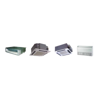
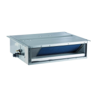
DC Inverter U-match Series Duct Type Unit
29
38 Pc Drive current error
39 Pd Sensor connecting protection
40 PE Temperature drift protection
41 PL Bus low voltage protection
42 PH Bus high voltage protection
43 PU Charge loop error
44 PP Input voltage abnormality
45 ee Drive memory chip error
Note: When the unit is connected with the wired controller, the error code will be simultaneously
shown on it.
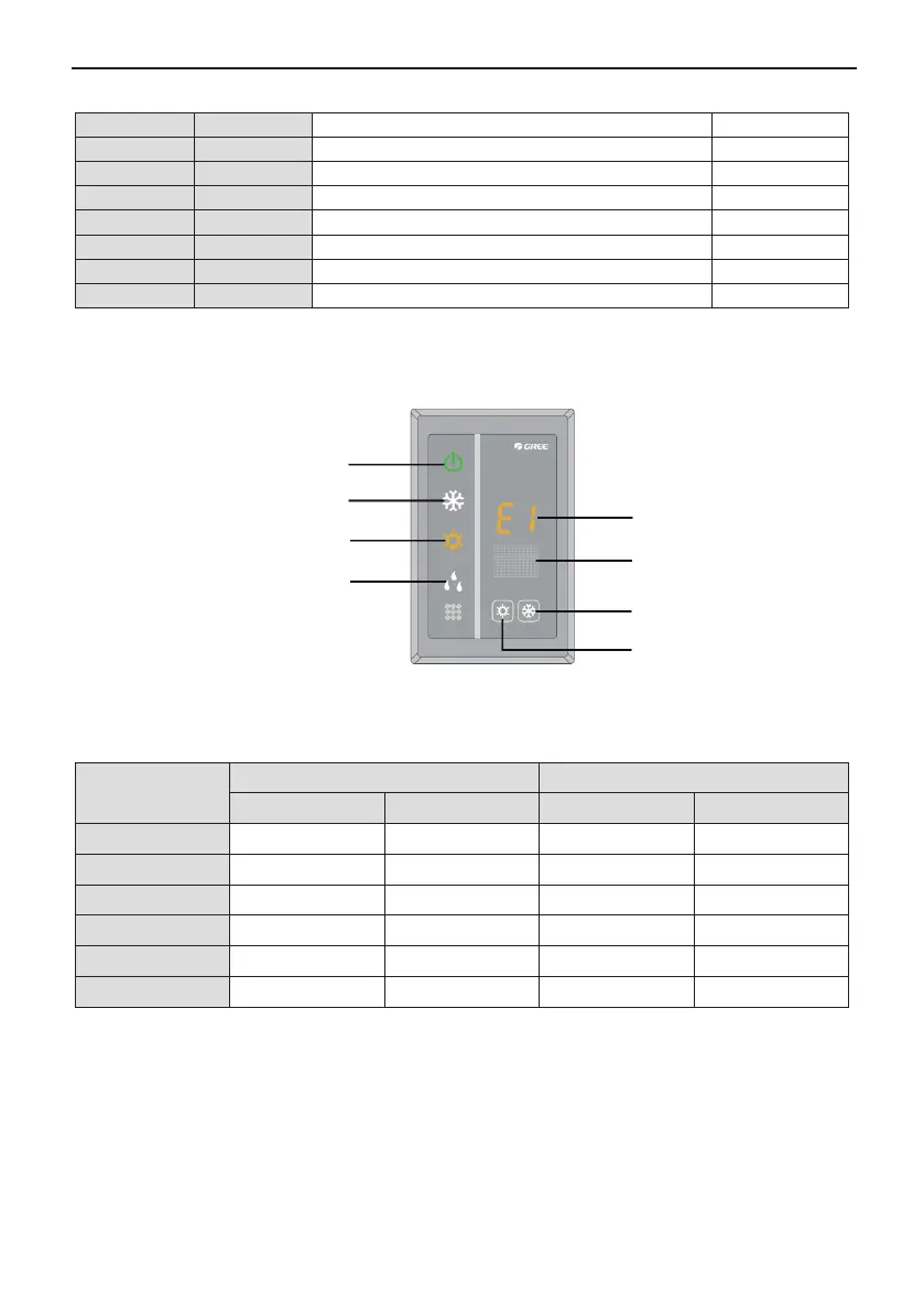
(2). Instructions to the Error Indicating Lamps on the Panel of the Duct Type Unit.
Power/Running
Indicating lamp
Cooling indicating lamp
Heating indicating lamp
Dehumidification
indicating lamp
“88” display
Receiver
“Cool” button
“Htat” button
Fig.47
6.2.Working Temperature Range
Table 12
Test Condition
Indoor Side Outdoor Side
DB(°C) WB(°C) DB(°C) WB(°C)
Nominal Cooling 27 19 35 24
Nominal Heating 20
−
7 6
Rated Cooling 32 23 48
−
Low Temp. Cooling 21 15 -15
−
Rated Heating 27
−
24 18
Low Temp. Heating 20
−
-10 -11
Note:
① .
The design of this unit conforms to the requirements of EN14511 standard.
② .
The air volume is measured at the relevant standard external static pressure.
③ .
Cooling (heating) capacity stated above is measured under nominal working conditions
corresponding to standard external static pressure. The parameters are subject to change
with the improvement of products, in which case the values on nameplate shall prevail.
④ .
In this table, there are two outside DB values under the low temp cooling conditions, and the
one in the brackets is for the unit which can operate at extreme low temperature.
 Loading...