DC Inverter U-match Series Cassette Type Unit
12
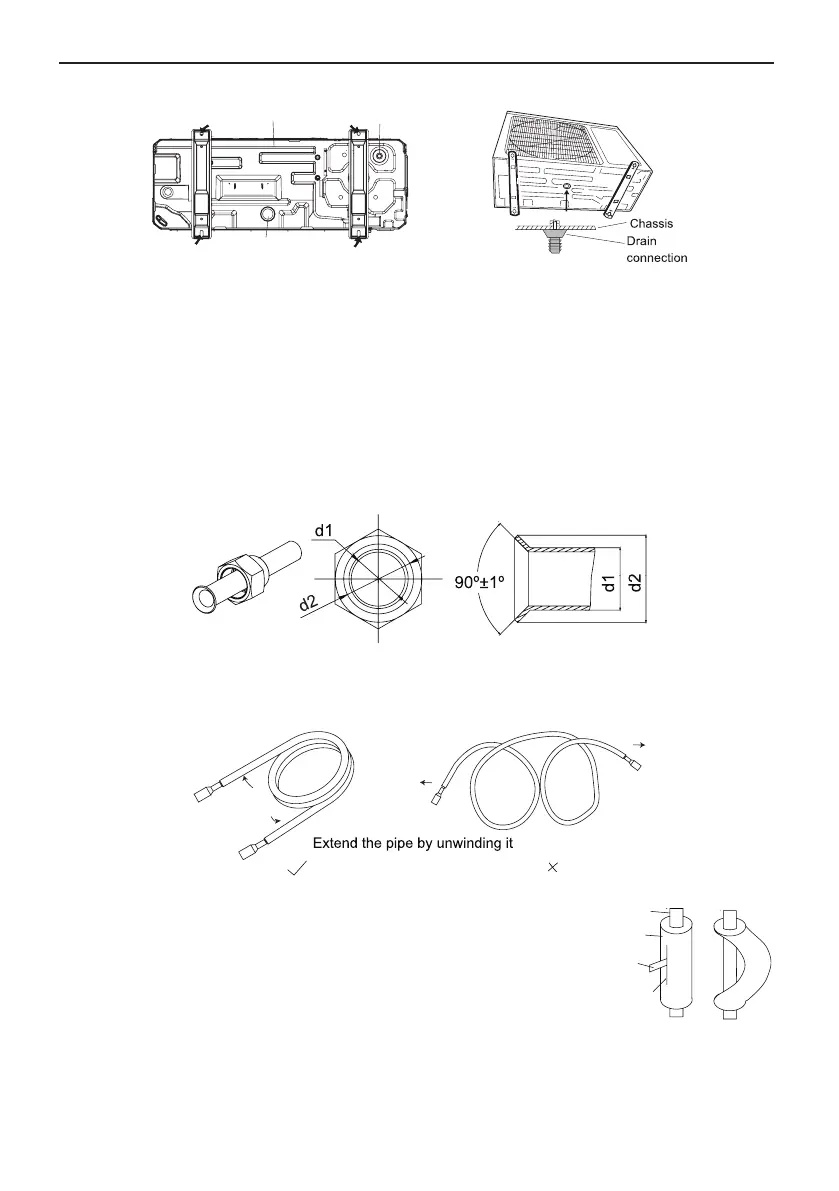
Bottom Drain cap
Drain pipe
mounting hole
Fig.11
4.3 Installation of the Connection Pipe
4.3.1 Flare Processing
(1). Cut the connection pipe with the pipe cutter and remove the burrs.
(2). Hold the pipe downward to prevent cuttings from entering the pipe.
(3). Remove the are nuts at the stop valve of the outdoor unit and inside the accessory bag of
the indoor unit, then insert them to the connection pipe, after that, are the connection pipe
with a aring tool.
(4). Check if the are part is spread evenly and there are no cracks (see Fig.12).
Fig.12
4.3.2 Bending Pipes
(1). The pipes are shaped by your hands. Be careful not to collapse them.
Fig.13
(2). Do not bend the pipes in an angle more than 90°.
(3). When pipes are repeatedly bent or stretched, the material
will harden, making it difcult to bend or stretch them any
more. Do not bend or stretch the pipes more than three
times.
(4). When bending the pipe, do not bend it as is. The pipe
will be collapsed. In this case, cut the heat insulating pipe with a sharp cutter as shown in
Fig.14, and bend it after exposing the pipe. After bending the pipe as you want, be sure to
put the heat insulating pipe back on the pipe, and secure it with tape.
Fig.14
Cutter
Cutt line
Heat insulating
pipe
 Loading...